


106
Western Digital Hard Disk Drive OEM Specification
UID
Name
Cmn
Name
Boolean Expression
Row
Start
Row
End
Column Start Column End
00 00 00 08
00 00 00 01
Anybody
“”
00 00 00 09 00 00 00 01
Null
Null
‘’’’
‘’’’
00 00 00 08
00 00 00 03
Makers
‘’’’
00 00 00 09 00 00 00 03
Null
Null
‘’’’
‘’’’
00 00 00 08
00 00 02 01
SID
“”
00 00 00 09 00 00 00 06
Null
Null
‘’’’
‘’’’
00 00 00 08
00 00 8C 03
SID_SetSelf
“”
00 00 00 09 00 00 00 06
Null
Null
“PIN”
“PIN”
00 00 00 08
00 00 8C 04
MSID_Get
“”
00 00 00 09 00 00 00 01
Null
Null
“PIN”
“PIN”
00 00 00 08
00 00 8C 05
SID_Set Makers
“”
00 00 00 09 00 00 00 06
Null
Null
“Enabled”
“Enabled”
00 00 00 08
00 00 8C 06
SID_Makers_SetDiag
“”
00 00 00 09 00 00 00 06
And
00 00 00 09 00 00 00 03
Null
Null
“PortLocked” “PortLocked”
00 00 00 08
00 00 8C 07
SID_Makers_GetDiag
“”
00 00 00 09 00 00 00 06
And
00 00 00 09 00 00 00 03
Null
Null
“PortLocked” “PortLocked”
00 00 00 08
00 00 8C 08
SID_SetPort
“”
00 00 00 09 00 00 00 06
Null
Null
“PortLocked” “PortLocked”
00 00 00 08
00 00 8C 09
SID_GetPort
“”
00 00 00 09 00 00 00 06
Null
Null
“LockOnReset” “PortLocked”
00 00 00 09
00 01 FF 01
ACE_Makers_Set_Enabled
“”
00 00 00 09 00 00 00 06
Null
Null
“”
“”
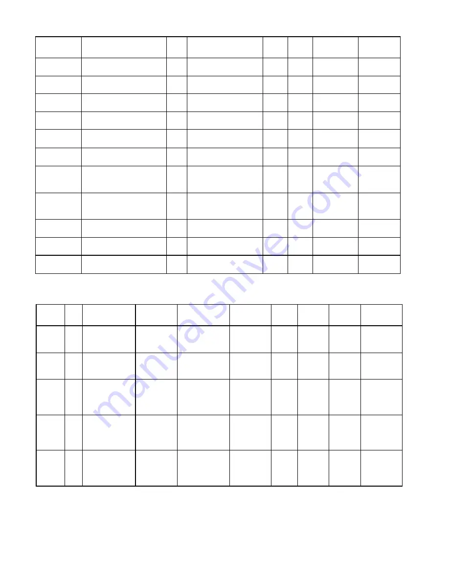
Table 83
Modified ‘Admin SP’ ACE Table
The 2 lines of the table are the additional entries required to implement the firmware download port.
Row
Number
UID
Invoking ID
Method ID
Common Name
ACL
Log
Add ACE
ACL
Remove
ACE ACL
GetACLACL
VU
VU
00 00 00 00
00 00 00 01
(This SP)
00 00 00 06
00 00 00 0C
(Authenticate)
Anybody
Authenticate
Admin SP
00 00 00 08
00 00 00 01
(Anybody)
None
Null
Null
00 00 00 08
00 00 00 01
(Anybody)
VU
VU
00 00 00 09
00 00 00 00
(Authority table)
00 00 00 06
00 00 00 08
(Next)
Makers-Next-
Authority table
00 00 00 08
00 00 00 03
(Makers)
None
Null
Null
00 00 00 08
00 00 00 03
(Makers)
VU
VU
00 00 00 09
00 00 00 01
(Anybody
Authority object)
00 00 00 06
00 00 00 06
(Get)
Anybody-Get-
Anybody
Authority Object
00 00 00 08
00 00 00 01
(Anybody)
None
Null
Null
00 00 00 08
00 00 00 01
(Anybody)
VU
VU
00 00 00 09
00 00 00 03
(Makers Authority
object)
00 00 00 06
00 00 00 06
(Get)
Anybody-Get-
Anybody
Authority Object
00 00 00 08
00 00 00 03
(Makers)
None
Null
Null
00 00 00 08
00 00 00 03
(Makers)
VU
VU
00 00 00 09
00 00 00 06
(SID Authority
object)
00 00 00 06
00 00 00 06
(Get)
SID-Get-SID
Authority Object
00 00 00 08
00 00 02 01
(SID)
None
Null
Null
00 00 00 08
00 00 02 01
(SID)
Table 84
Modified ‘Admin SP’ Access Control Table (part 1 of 2)


