Section AIS‐RM3‐20B
030‐101806 Rev. A
R
1310IBRA
2
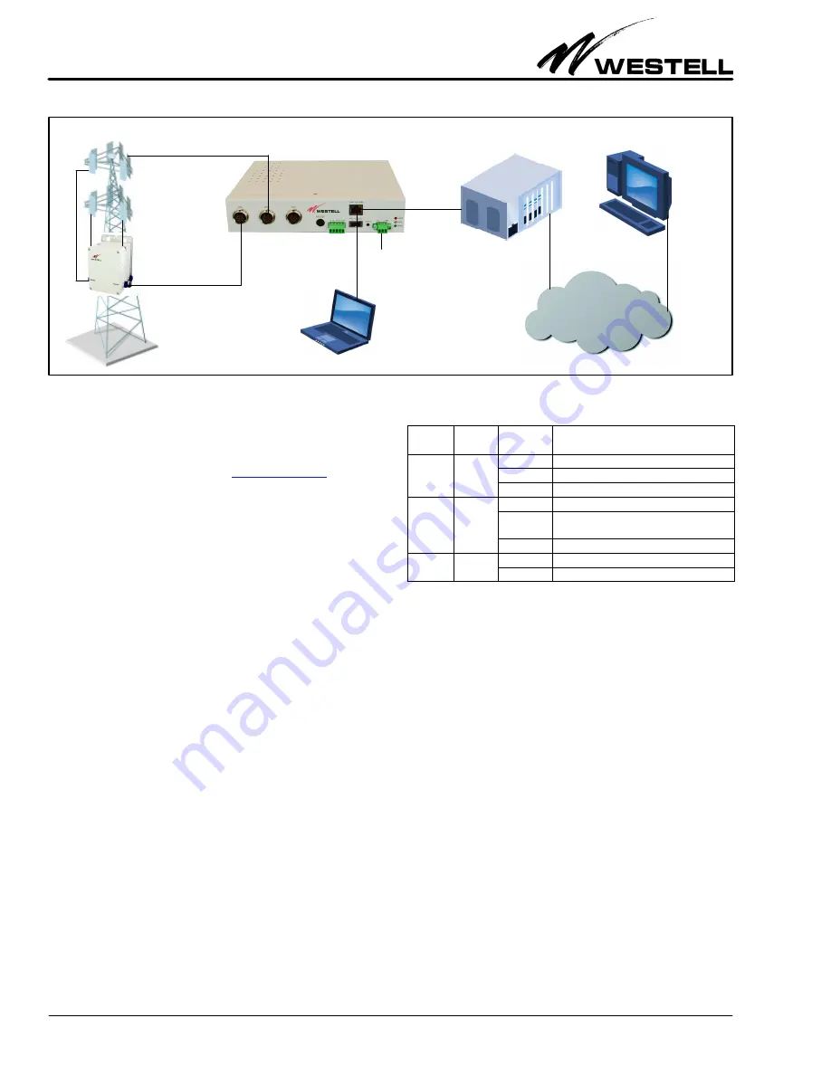
Figure 3. AISG‐RM3 Controller Sample Application
IP Network
Base Station
Off
−
site
control
Laptop
(on
−
site
control)
AISG-RM3 Controller
RET Antenna
TMA
Power
Input
Default IP Address:
192.168.0.30
Default User Name:
admin
Default Password:
admin
Latest documentation location:
2.
FEATURES & OPTIONS
The features and highlights of the Westell AISG‐RM3 are lis
ted below. See the paragraphs that follow in this section for
additional information on some of the features.
2.1
Highlights and Benefits
The controller provides the following benefits.
S
Supports both AISG v1.1 and AISG v2.0 for remote control
and monitoring of AISG line devices
S
Remote setting of TMA gain and mode
S
Remote adjustment of RET antenna tilt angle
S
RET antenna configuration and calibration
S
Management of base station site information such as site
ID, name, location and contact
S
Management of user accounts with multiple security levels
S
Power saving mode to suspend the power output of AISG port
2.2
Front Panel Features
On the front panel of the controller are eight ports (including
3 AISG ports to connect to AISG line devices), a reset button,
and three LEDs, as shown in Table 1 and Table 4 below and ex
plained in the paragraphs that follow.
LED
Color
State/
Status
Description
ALM
(alarm)
Red
Steady
AISG RM3 cannot ping default gateway
Flashing
Alarm present.
Off
No alarm present
RUN
Yellow
Steady
AISG RM3 busy
Flashing
Indicates system is running or ready for
use.
Off
PWR
(power)
Green
Steady
On steady when power is present.
Off
Unit not powered.
Table 1. LED Conditions and States
2.2.1
LEDs
Three LEDs are located on the front panel of the AISG‐RM3.
Their states and functions are explained in Table 1.
2.2.2
AISG Ports
Three standard, female, 8‐pin, AISG ports are provided on the
front of the controller. Each AISG port can control up to 8 an
tenna line devices by using daisy‐chained cables.
2.2.3
RS‐232 Port
The round RS‐232 port on the controller is used to access the
console or command line interface. See Figure 4 for the
pin‐outs of the DB‐9 RS‐232 connector and for an illustration
of the pin locations. See Part 7 for more information on this in
terface.
2.2.4
Alarm Connector
A pluggable alarm connector is provided for connection with
external alarm reporting equipment. The alarm output is a con
tact relay. Five port holes for stripped wires are provided on the
connector, with screws that accept a small slotted screwdriver
for tightening and securing the alarm wires which are inserted


