
030-101868 Rev A
Section A90-DCP10X10
________________________________________________________________________________
Page 3 of 6
1509IARA
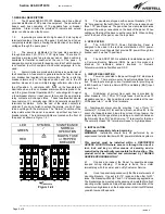
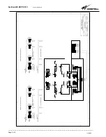
Figure 4.2.1
4.3.
Mount the panel on the equipment rack using the thread
forming #12-24 rack mounting screws and tooth lock washers
provided. If you want the cables to exit the top of the panel, use
standard lugs and discard the top protective shield. If you want
the cabling to exit the back of the panel, use right angle lugs and
discard the back protective shield.
Rack Mount Instructions:
Elevated Operating Ambient
- For closed or multi-unit rack
assemblies, the operating ambient may be greater than room
ambient. Take care to install the equipment in an environment
compatible with the maximum ambient temperature (Tma)
specified by the manufacturer.
Reduced air flow
- Installation of the equipment in a rack should
be such that the amount of air flow required for safe operation is
not compromised.
Mechanical Loading
- Mounting of the equipment in the rack
should be such that a hazardous condition is not achieved due to
uneven mechanical loading.
Circuit Overloading
- Consideration should be given to the
connection of the equipment to the supply circuit and the effect
that overloading of the circuits might have on overcurrent
protection and supply wiring. Appropriate consideration of
equipment nameplate ratings should be used when addressing
this concern.
Reliable earthing
- Reliable earthing of rack-mounted equipment
should be maintained. Particular attention should be given to
supply connections other than direct connections to the branch
circuit.
WARNING:
For safety reasons all wiring should be done with all
power sources removed (when possible).
Note:
A readily accessible disconnect device shall be
incorporated in the building installation wiring.
4.4.
Remove the distribution fuse feeding the input cables
that are to be connected to the new panel. Remove the 2 outer
nuts on each side and slide the return bar assembly off the unit
to access the input terminals. Attach the input cables to the input
terminals in accordance to the National Electrical Code,
ANSI/NFPA, and Canadian Electrical code. Hook up the input
cables to the input terminals (“BAT” & “RTN” for each bus). Each
high current input terminal can accept 2 - two-hole compression
lug (3/8” on 1”, torque to 20 ft-lbs). Once the inputs are
connected, re-install the ground bar assembly, and the 4 nuts that
hold it in place.
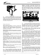
Figure 4.4.1
4.5.
The battery outputs (BAT) and ground returns (RTN) are
also located on the back of the panel. Each fuse/breaker position
and terminal position is numbered 1-10. Connect your load side
equipment to the panel, and record which equipment is
connected to which input on the designation card (supplied).
4.6.
All battery return (“RTN”) connections are also
terminated using two-
hole lugs (1/4” on 5/8” centers). Note, these
returns are isolated from the chassis frame.
4.7.
This panel has Bus A, and Bus B alarm contacts. Each
alarm has a common (C), normally open (NO) and normally
closed (NC) alarm contact. In an alarm the “C” contact will short
to the “NO” contact, and the “NC” will open. Wire-wrap the alarm
connections as per your alarm system requirements. The alarm
contacts are limited to 1A through an auto resettable fuse within
the panel. The panel comes preconfigured to work with fuse
alarms and mid-trip style breaker alarms. If you wish to use
standard non mid-trip breakers, adjust the shunt on the pluggable
alarm card to the “NON MID-TRIP” position.
4.8.
Chassis Ground: For safety reasons, and as
recommended by NEBS, the chassis should be electrically
connected to the rack ground. From step 4.3. the panel should
already be ground to the rack via the #12-24 thread forming rack
screws and outside tooth lock washers. In addition to grounding
via the mounting brackets, it is recommended you ground the
chassis using a ground cable and the two ¼” bolts on the inner
sidewall of the chassis (1/4” bolt torque; 5.5ft-lbs or 7.5Nm).
Consult the National Electric Code, ANSI/NFPA, and Canadian
Electrical code for AWG sizes.
4.9.
The input wiring feeding this panel should be protected
by a Listed fuse/breaker rated for at least 60Vdc, with a trip rating
of 750 Amps Max. With input wiring connected and this input fuse
installed, the panel should power up with the Normal Operation
LED
illuminated and without any red LEDs
!
illuminated,
and the relays should be in the “Normal” state (“C” connected to
“NC”).