

Select the Data Assemblies screen using View | Data Assemblies or the Data Assemblies
button.
A Data Assembly is a user-defined collection of parameters that the Bus
Module collects from its Loop Modules so that the master device (PLC, SCADA or HMI)
can collect the required parameter data in one message transaction.
There are two user definable data assemblies. These are 1)
Read
-
parameters that are to
be transferred from the MLC 9000+ to the supervisory system
and 2)
Write
-
parameters
that are to be transferred from the supervisory system to the MLC 9000+.
In the left hand column are all the parameters that can be mapped to the data assemblies
for transfer to or from the supervisory system and on the right are the two data assemblies.
To populate the data assemblies select a parameter from the list then drag and drop it into
the read or write tables. MLC 9000+ will not allow read only parameters to be placed into
the write data assembly.
Word parameters are shown with a
W
and bit parameters are shown with a
B
. If a bit
parameter is dragged onto a word register the register is converted into 16 bits. The full 16
bits can then be filled with any combination of bit parameters. If a word parameter is placed
into that bit register then it is then converted back to a word register and the bit
configuration is lost.
A summary of the data assembly
information can be created by
selecting the ‘summary’ icon
in
the tool bar
Once the system has been configured it can be saved by clicking on the save
icon in
the tool bar or navigate to File | Save as.
Some Fieldbus protocols require a GSD/EDS file for configuration of the master device.
MLC 9000+ Workshop generates this file once the data assemblies have been populated.
Click on the create GSD/EDS icon
in the tool bar this will activate the create
GSD/EDS wizard that will guide you through the creation of the GSD/EDS file.
To download the configuration to the MLC 9000+ click on the
icon in the tool bar, this
will activate the download wizard which will guide you through the download process.
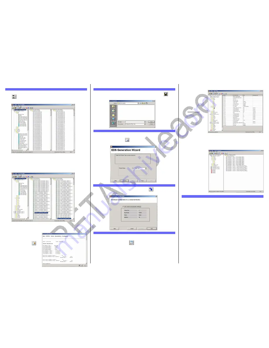
The MLC 9000+ system can be adjusted using the expert view and monitored using the
Monitoring view.
Adjusting Parameters in Expert view
The expert view contains all the parameters that can be edited in a full system.
In the left hand column are the modules as configured in the system configuration, by
clicking on the + sign next to the module the tree view is expanded and all the parameter
classes are displayed.
When a class is selected all the parameters for that class are displayed on the right.
Clicking on the value of a parameter enables that parameter to be edited. When all
required parameter changes have been made the configuration can be download to the
MLC 9000+ by clicking on the Download configuration icon.
To work online select
Settings | Work Online.
This will then make the
expert view live so that
any changes made will be
downloaded to the MLC
9000+
immediately
.
WARNING:
Care must be taken when working online as changing certain parameters may
cause others to change automatically (i.e. when the input range is changed the scaling is
defaulted)
CAUTION:
When working online it is advised that steps are taken to ensure damaging
conditions can not be caused.
Monitoring View
In the left hand column are
all the parameters that can
be viewed, organised by
module and class. To
monitor a variable double
click the parameter name.
It will then appear in the
right hand column.
.
Your PC should meet the following minimum requirements for satisfactory operation of the
software:
Windows 2000
PC with 400 megahertz (MHz) or higher processor clock speed recommended; 133-MHz
minimum required;*
128 megabytes (MB) of RAM or higher recommended (64 MB minimum supported)
64 megabytes (MB) of available hard disk space.*
Super VGA (800 × 600) or higher resolution video adapter and monitor
CD-ROM or DVD drive
Keyboard and Mouse or compatible pointing device
Windows XP
PC with 800 megahertz (MHz) or higher processor clock speed recommended; 233-MHz
minimum required;*
256 megabytes (MB) of RAM or higher recommended (64 MB minimum supported)
64 megabytes (MB) of available hard disk space.*
Super VGA (800 × 600) or higher resolution video adapter and monitor
CD-ROM or DVD drive
Keyboard and Mouse or compatible pointing device
* Actual requirements will vary based on your system configuration and the applications
and features you choose to install. Additional available hard disk space may be required if
you are installing over a network.
6. CONFIGURING THE FIELDBUS COMMUNICATIONS (DATA ASSEMBLIES)
8. GENERATING THE GSD/EDS FILE
9. DOWNLOADING THE CONFIGURATION TO THE MLC 9000+
7. SAVING A SYSTEM CONFIGURATION
10. ADJUSTING AND MONITORING A LIVE SYSTEM
11. MLC 9000+ WORKSHOP SYSTEM REQUIREMENTS


