background image

1.  Connect the GREEN wire of the included accessory cable to the GPS DATA OUTPUT (-) WIRE or the GROUND WIRE on your 

GPS receiver.

2.  Connect the YELLOW wire of the included accessory cable to the GPS DATA OUTPUT (+) WIRE on your GPS receiver.
3.  Be certain all wire connections are secure and that all open wires are adequately covered.

NOTE: to extend the life of the radio, use waterproof tape to seal electrical connections. 

4.  Plug the accessory cable into the accessory cable pigtail on the back of your radio.

GPS Verification

If the GPS receiver is correctly connected and it transmits valid data, the display shows 

GPS Data OK

. Press

 ENT-1W25W

 to 

open the GPS status screen and see detailed GPS data:

16

06/20  11:00:00
208

o

    30. 0 KT

 35

o

   40. 610 N

139

o

   46. 564 E

GPS Data: External

Date

Time

Current 

channel

Course

Latitude

Longitude

Speed

Status

If the GPS does not send coordinates within 30 minutes, an audible alert sounds once and the display shows 

Input GPS

. This message 

remains until the coordinates are updated.
After 4 hours, the audible alert sounds again if no coordinates are received and the GPS is connected. After 23.5 hours, the radio 

deleted the current coordinates and displays 

Input GPS

.

See page 11 to manually set the GPS coordinates. 

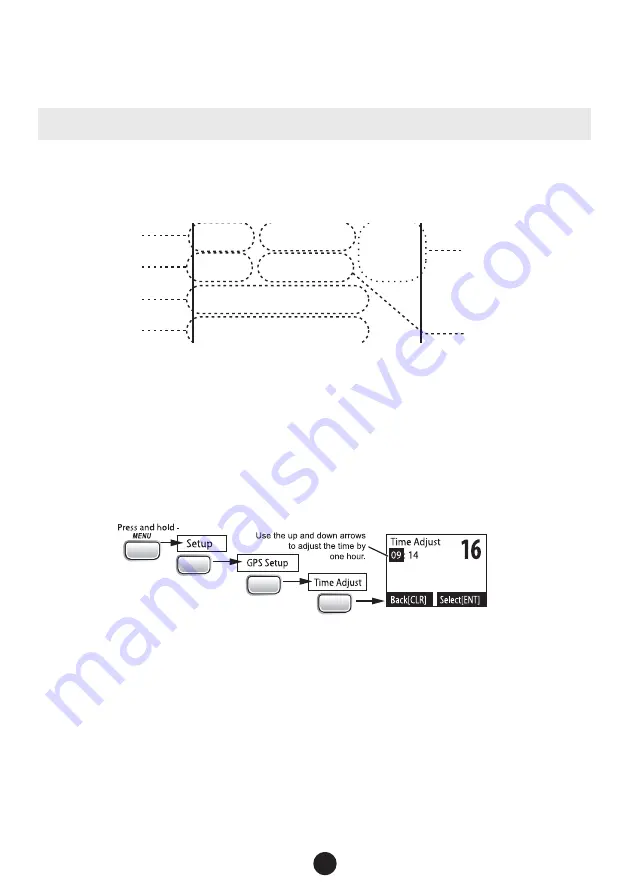
Configuring the GPS

If the radio is receiving valid GPS data, it will automatically set the clock to your local time based on the GPS location. You can 

adjust your local time forward or back one hour if necessary (for example, if you are close to the border of a time zone); you can 

also adjust for Daylight Savings Time. 
Follow the steps below to adjust the time:  

1. 

CALL

ENT

1W/25W

ENT

1W/25W

ENT

1W/25W

Display the normal menu and choose the 

Setup

 sub-menu. 

2.  Select 

GPS Setup

 and then choose 

Time Adjust

3.  The display shows your current local time. To adjust the time forward one hour, use 

CHANNEL UP

. To adjust the time back 

one hour, use 

CHANNEL DOWN

 button. Press 

ENT-1W/25W

 button when you are finished. 

4.  The display prompts you to confirm the setting: choose 

Set

 to save the new time or 

Cancel

 to exit time setup without saving. 

The radio returns to the GPS Setup menu. 

5.  If your local area observes Daylight Savings Time, choose 

Daylight Save

 and press the 

ENT-1W/25W

 button. 

6.  If Daylight Savings Time is currently in effect, select 

On

. If Daylight Savings Time is not currently in effect, select 

Off

7.  Press 

ENT-1W/25W

. The radio activates the new time setting and returns to the GPS Setup menu. 

Connecting to a Chartplotter

Your radio provides a standard NMEA0183 GPS output that you can connect to a chartplotter. When it receives another boat’s 

position data in a DSC call, the radio sends the position data to the chartplotter so you can see the location: 

VHF490 RADIO

1-800-BOATING

25

Summary of Contents for 18114496

Page 1: ...VHF490 FIXED MOUNT MARINE RADIO MODEL 18114496 Owner s Manual...

Page 2: ...y MAYDAY MAYDAY MAYDAY 4 Say THIS IS name or call sign of your boat 5 Say MAYDAY name or call sign of your boat 6 Tell where you are what navigational aids or landmarks are near or read the latitude a...

Page 3: ...Features 12 What is an MMSI Number 13 Entering MMSI Numbers 13 Using the Directory 14 Making DSC Calls 15 Making an Automatic Distress Call 17 Receiving a DSC Call 17 Test Calls 18 Position Request a...

Page 4: ......

Page 5: ...Administration NOAA weather channel watch Sounds a warning tone when a hazard alert is issued for your area Explanation of Terms Term What it Means DSC Digital Selective Calling A VHF radio standard f...

Page 6: ...the channels 16 9 TRI 1st press Go to Channel 16 2nd press Go to Channel 9 3rd press Go back to the original channel Go into Triple Watch or Dual Watch mode see page 10 CLR SCAN Go to previous menu o...

Page 7: ...nnel Talk on a channel Turning on the Radio Turn the VOLUME PWR knob clockwise to turn on the radio As it powers on the radio displays the user MMSI number if there is no MMSI set the radio displays M...

Page 8: ...nd 9 Press and hold 16 9 TRI for two seconds Dual Checks for activity on channel 16 every two seconds You want to monitor a channel yet maintain a watch on channel 16 Change Triple Watch to Dual Watch...

Page 9: ...heck the weather channel while you are actively transmitting it waits until your transmission is finished and then checks the weather channel To turn Weather Alert Watch on or off press and hold CALL...

Page 10: ...iple Dual watch on Status icons Using the radio in scan mode You cannot transmit while in scan mode You must have two or more channels in memory to start a scan To save a channel into memory select th...

Page 11: ...scans the next channel wx Memory Channel Scan 08 25 24 17 15 14 13 12 11 10 20 Weather Mode In cooperation with the FCC NOAA also uses the weather channels to alert you of other hazards besides weath...

Page 12: ...ting On or Off Weather mode with Triple and Dual Watch If you activate Triple Watch while operating in weather mode the radio checks channels 16 and 9 every two seconds with Dual Watch turned on the r...

Page 13: ...ctual radio transmissions through Weak signals No Squelch Medium Squelch High Squelch Strong signals Noise While listening to a channel adjust the SQUELCH knob until the noise is filtered out and you...

Page 14: ...Triple Watch or Dual Watch In Triple Watch mode the radio briefly checks channels 16 and 9 every two seconds In Dual Watch mode the radio checks channel 16 only Generally Triple Watch is used in area...

Page 15: ...ancel this code select No The radio returns to the list of FIPS codes 7 To change an existing FIPS code select the code you want to change 8 To delete the FIPS code select Delete To edit the code sele...

Page 16: ...o the other station along with the voice channel you requested If the other station accepts your call both radios automatically switch to the requested voice channel so you can talk to the other stati...

Page 17: ...e steps below to enter your individual or user MMSI number into the radio 1 CALL ENT 1W 25W ENT 1W 25W ENT 1W 25W Display the normal menu and choose the Setup sub menu 2 Select User MMSI If an MMSI nu...

Page 18: ...directory 1 Press CALL MENU to display the call menu 2 Select Directory The screen displays any previously entered MMSI numbers and names 3 To add a new MMSI number to the directory select New 4 The...

Page 19: ...entially four different types of DSC voice calls Call type What it does When to use it Distress Alerts all stations that you need assistance and sends them your current position In an emergency only I...

Page 20: ...l the call select Cancel 6 The radio automatically switches to channel 70 to transmit the call request When the other station accepts the call both radios switch to the selected response channel for v...

Page 21: ...or three seconds Undesignated Sinking Fire Adrift Flooding Abandoning Collision Piracy Armed Grounding Overboard Capsizing 3 If no MMSI number has been programmed the radio prompts you to enter your M...

Page 22: ...ry code communication channel number All Ships MMSI or name category code communication channel number Group MMSI or name category code communication channel number Individual MMSI or name category co...

Page 23: ...ompts you to enter the MMSI number you want to call Enter the MMSI number the same way you enter directory entries see page 14 Enter all nine digits and press ENT 1W 25W button 4 The radio displays th...

Page 24: ...rectory use CHANNEL UP and CHANNEL DOWN to choose the directory entry you want to contact and press ENT 1W 25W If you want to contact a station that is not in your directory select Manual The radio pr...

Page 25: ...requesting assistance or using an all ships call to give a safety warning you can send your current position so other stations know where you are 1 Press CALL MENU to display the call menu 2 Select P...

Page 26: ...annel to make it easier for you to use see the channel lists beginning on page 30 for the default channel names To rename a channel follow the steps below 1 Display the normal menu and choose the Setu...

Page 27: ...ng bracket 2 Position the radio into the desired location Mark the edges of the bracket on the mounting surface 3 Actual product image may vary slightly Remove the mounting bracket drill template from...

Page 28: ...37 for more details In summary the FCC recommends that antennas up to 3 dB be installed a minimum of 3 feet from any occupied location antennas over 3 dB should be installed at least 6 feet away 5 Co...

Page 29: ...If the radio is receiving valid GPS data it will automatically set the clock to your local time based on the GPS location You can adjust your local time forward or back one hour if necessary for examp...

Page 30: ...smit except in the case of an emergency A defective antenna may cause damage to your radio You are responsible for continued FCC technical compliance of your radio You should arrange for periodic perf...

Page 31: ...iss which FIPS codes are affected For your safety the radio triggers the alert tone and switches to the weather channel when this happens I can t make Group DSC calls Make sure the Group MMSI was ente...

Page 32: ...eeds EIA standards RS152B and RS204C FCC Approvals Type accepted under part 80 of the Rules meets Great Lakes Agreement and party boat requirements Transmitter Power Output 1 watt or 25 watt user sele...

Page 33: ...CE MARINE OPERATOR calls to the marine operator at a public coast station Marine operators can connect you to the telephone network so you can make and receive calls There is usually a charge for this...

Page 34: ...s 20m length maintain a listening watch on this channel in US waters 14 x x x 156 700 156 700 Port Operation VTS in some areas 15 x Inhibit 156 750 Environmental Receive Only 15 x x 156 750 156 750 In...

Page 35: ...Operations Canada 1 Watt Only 67 x x x 156 375 156 375 US Commercial Bridge to Bridge VTS in some areas Canada Search and Rescue Commercial in some areas Non Commercial on West Coast 68 x x x 156 425...

Page 36: ...162 4500 162 450 MHz WX06 162 5000 162 500 MHz WX07 162 5250 162 525 MHz WX08 161 6500 161 650 MHz WX09 161 7750 161 775 MHz Emergency Alert System SAME Information Types of events A WARNING is an ev...

Page 37: ...ter Storm Warning WSW Warning National Information Center NIC Test Avalanche Watch AVA Watch Avalanche Warning AVW Warning Child Abduction Emergency CAE Emergency Civil Danger Warning CDW Warning Civi...

Page 38: ...tement Unrecognized Statement S Statement Unrecognized Warning W Warning No Response Event Code TXB Transmitter Backup On TXF Transmitter Carrier On TXO Transmitter Carrier On TXP Transmitter Primary...

Page 39: ...e radio uses only the RMC sentence NOTE 3 Status data is used to check whether the GPS data is valid or invalid NMEA Output When the radio receives a DSC call Distress Position Reply or Position Send...

Page 40: ...are designed to provide reasonable protection against harmful interference in a residential installation This equipment gen erates uses and can radiate radio frequency energy and if not installed and...

Page 41: ...the following guidelines to ensure a suitable distance between the antenna and persons close by Small whip antennas 3 dB or smaller should be installed keeping at least a two foot separation distance...

Page 42: ...ublished specifications and the user s manual What Do I Do If I Need Warranty Service Before the warranty expires please call us at 1 800 BOATING 1 800 262 8464 Please also have your serial number or...

Page 43: ...How State Law Relates to the Warranty This warranty gives you specific legal rights and you may also have other rights which vary from state to state 43000 1851 Rev 12 13 VHF490 RADIO 1 800 BOATING 39...

Page 44: ...NOTES VHF490 RADIO 1 800 BOATING 40...

Page 45: ...VHF490 RADIO 1 800 BOATING 41...

Page 46: ...VHF490 RADIO 1 800 BOATING 42...

Page 47: ...VHF490 RADIO 1 800 BOATING 43...

Page 48: ...www westmarine com Printed in Vietnam U01UT655ZZA 0...

Reviews: