WARNING DECAL PLACEMENT
The decal shown at the right has
been placed on the resistance
cylinder of your CARDIO GLIDE
PLUS.
If the decal is missing, or if it is not
legible, please call our Customer
Service Department, toll-free, to
order a free replacement decal
(see ORDERING REPLACEMENT
PARTS on the back cover of this
manual). Apply the decal in the
location shown at the right.
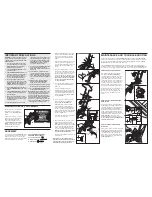
1. Raise the Handlebar Frame (7) to the
position shown. Hold the Handle (20)
and hook the Link Arms (4) onto the
lower Rollers (33) on the Handlebar
Frame.
Press two Round Endcaps (8) onto the
stabilizer at the front of the Frame (6).
Press two Round Endcaps onto the sta-
bilizer at the rear of the Frame (not
shown).
2. Turn the Seat Knob (38) to loosen it.
Pull down the Seat Knob and slide the
Seat (3) onto the Seat Frame (5). Slide
the Seat to the desired position and
release the Seat Knob. Retighten the
Seat Knob.
Push on the Seat to make
sure that the Seat Knob is engaged
in one of the holes in the underside
of the Seat Frame.
3. Press the two Domed Endcaps (13)
onto the upper end of the Handlebar
Frame (7).
Insert the Handlebar (2) into the
Handlebar Frame (7). The sides of the
Handlebar must bend toward the Seat
(not shown). Tighten the four #8 x 1/2”
Screws (16) into the Handlebar Frame
and the Handlebar.
4. Connect the Sensor Wire (15) to the
wire on the Monitor (1).
Insert all
excess wire into the Frame (6).
Hold the Monitor (1) with both hands,
and slide it down onto the Frame (6).
Refer to the inset drawing. Be sure that
the side of the Monitor is between the
Frame and the indicated 1/2” Dome Cap
(29). Push the 1/2” Dome Cap against
the side of the Monitor.
Slide the Foam Pad (26) onto the end of
the 1/2” x 6 1/2” Axle (39).
5. Apply a small amount of grease to the
shaft on the right side of the Pedal
Frame (32). Slide a Pedal (12) onto the
shaft. Make sure that the Pedal is turned
so the plastic tube is facing the Pedal
Frame. Using the included pedal tool,
tap a 1/2” Push Nut (30) onto the shaft.
Make sure that the Push Nut is turned
as shown in the inset drawing.
Attach the other Pedal (not shown) in the
same manner.
Note: Extra 1/2” Push Nuts (30) may
have been included. Save the Push Nuts
and the pedal tool in case replacement
Push Nuts are needed in the future.
IMPORTANT PRECAUTIONS
WARNING: To reduce the risk of serious
injury, read the following important pre-
cautions before using the WESLO
®
CAR-
DIO GLIDE PLUS.
1. It is the responsibility of the owner
to ensure that all users of the CAR-
DIO GLIDE PLUS are adequately
informed of all precautions.
2. Use the CARDIO GLIDE PLUS only
on a level surface.
3. The CARDIO GLIDE PLUS features a
precision resistance cylinder; due to
the nature of resistance cylinders
the floor underneath should be cov-
ered in case of slight oil leakage.
4. Wear appropriate clothing when
exercising; do not wear loose cloth-
ing that could become caught in the
CARDIO GLIDE PLUS. Always wear
athletic shoes for foot protection.
5. Keep small children and pets away
from the CARDIO GLIDE PLUS at all
times.
6. The CARDIO GLIDE PLUS should not
be used by persons weighing more
than 250 pounds.
7. Before exercising, make sure that
the link arms are securely connected
to the upper or lower rollers on the
handlebar frame.
8. After adjusting the position of the
seat, push on the seat to make sure
that the seat knob is engaged in one
of the holes in the underside of the
seat frame. Do not use the CARDIO
GLIDE PLUS unless the seat is
securely locked in position.
9. Do not use the CARDIO GLIDE PLUS
when the resistance cylinder is
below room temperature or damage
may occur.
10. The resistance cylinder becomes
very hot during use. Allow the resis-
tance cylinder to cool before touch-
ing it. When adjusting the resistance,
touch only the resistance adjustment
collar.
11. Always keep your back straight
when using the CARDIO GLIDE
PLUS. Do not arch your back.
12. Inspect and tighten all parts regularly.
Replace any worn parts immediately.
13. Use the CARDIO GLIDE PLUS only
as described in this manual.
WARNING: Before beginning this or any
exercise program, consult your physi-
cian. This is especially important for
persons over the age of 35 or persons
with pre-existing health problems. Read
all instructions before using. ICON
assumes no responsibility for personal
injury or property damage sustained by
or through the use of this product.
Place all parts of the CARDIO GLIDE PLUS
in a cleared area and remove the packing
materials. Do not dispose of the packing
materials until assembly is completed. Read
each step carefully before beginning.
THE FOLLOWING TOOLS ARE
REQUIRED FOR ASSEMBLY:
The included pedal tool
A phillips screwdriver
A rubber mallet
ASSEMBLY
1
33
4
8
6
20
7
13
7
2
16
38
3
5
3
2
1
4
15
39
6
32
30
Pedal
Tool
32
Apply
Grease
Plastic
Tube
5
Teeth
29
1
Front View
30
12
26
MAINTENANCE AND TROUBLE-SHOOTING
Inspect and tighten all parts of the CARDIO GLIDE PLUS regularly. The CARDIO GLIDE
PLUS can be cleaned with a soft, damp cloth. Keep liquid away from the monitor. Keep the
monitor out of direct sunlight or the display may be damaged. When storing the CARDIO
GLIDE PLUS, remove the batteries from the monitor.
The CARDIO GLIDE PLUS features a precision resistance cylinder; due to the nature of
resistance cylinders, it is recommended that the floor underneath the CARDIO GLIDE PLUS
be covered in case of slight oil leakage. A small amount of oil leakage is normal during use.
HOW TO REPLACE THE BATTERIES
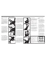
If the display of the Monitor (1) becomes
dim, the
two L1154 watch batteries
should be replaced. Lift the Monitor off the
Frame (6). Disconnect the Sensor Wire
(15) from the Monitor. Remove the four
screws from the back cover of the Monitor
and remove the back cover (see the inset
drawing). Push the two old batteries out of
the battery clips, noting which way each
battery is turned. Insert two new batteries.
Reattach the back cover of the Monitor (1).
Connect the Sensor Wire (15) to the
Monitor. Insert all excess wire into the
Frame (6). Press the Monitor onto the
Frame.
HOW TO ADJUST THE MAGNET AND
REED SWITCH
If the monitor displays incorrect feedback,
the Magnet (27) and the Reed Switch (15)
should be checked. Pivot the Pedal Frame
(32) until the Magnet is aligned with the
Reed Switch. Slightly loosen the #8 x 3/4”
Screw (18) in the Reed Switch. Slide the
Reed Switch slightly closer to the Magnet.
Tighten the #8 x 3/4” Screw. Exercise on the
CARDIO GLIDE PLUS for a moment.
Repeat until the monitor displays correct
feedback.
Make sure that the Magnet does
not hit the Reed Switch.
HOW TO LUBRICATE THE CARDIO
GLIDE PLUS
Every three months, a small amount of light
multi-purpose oil should be applied to the
CARDIO GLIDE PLUS. Apply a few drops
of oil between the dome caps and the
frame in the locations shown at the right.
Make sure to apply oil to both sides of the
CARDIO GLIDE PLUS.
Apply Oil
32
27
15
6
1
Screws
Batteries
32
27
18
15
15
1


