background image

19

TROUBLESHOOTING

Most treadmill problems can be solved by following the steps below. Find the symptom that applies, and

follow the steps listed. If further assistance is needed, please see the front cover of this manual.

PROBLEM: The power does not turn on

SOLUTION:

a. Make sure that the power cord is plugged into a surge suppressor, and that the surge suppressor

is plugged into a properly grounded outlet (see page 12). Use only a single-outlet surge suppres-

sor that meets all of the specifications described on page 12.

IMPORTANT: The treadmill is not

compatible with GFCI-equipped outlets.

b. After the power cord has been plugged in, make sure that the key is inserted into the console.

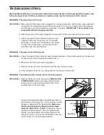
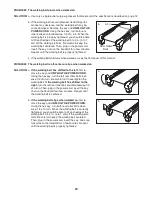
c. Check the reset/off circuit breaker located on the

treadmill frame near the power cord. If the switch

protrudes as shown, the circuit breaker has tripped.

To reset the circuit breaker, wait for five minutes,

and then press the switch back in.

PROBLEM: The power turns off during use

SOLUTION:

a. Check the reset/off circuit breaker (see the drawing above). If the circuit breaker has tripped, wait

for five minutes and then press the switch back in.

b. Make sure that the power cord is plugged in.

c. Remove the key from the console. Reinsert the key into the console.

d. If the treadmill still will not run, please see the front cover of this manual.

PROBLEM: The displays of the console do not function properly

SOLUTION:

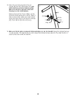
a. Remove the key from the console and

UNPLUG THE

POWER CORD.

Remove the three indicated Hood

Screws (20) and two Foot Rail Screws (25). Then,

carefully remove the Hood (65).

Locate the Reed Switch (89) and the Magnet (62) on

the left side of the Pulley (71). Turn the Pulley until the

Magnet is aligned with the Reed Switch.

Make sure

that the gap between the Magnet and the Reed

Switch is about 1/8 in. (3 mm).

If necessary, loosen

the Reed Switch Screw (3), move the Reed Switch

slightly, and then retighten the Screw. Reattach the

Hood (not shown), and run the treadmill for a few min-

utes to check for a correct speed reading.

25

20

65

a

Tripped

Position

Reset

Position

c

62

3

89

Top View

1/8 in.

71

Summary of Contents for Cadence J3.8 Treadmill

Page 1: ...fitness tips and much more QUESTIONS As a manufacturer we are com mitted to providing complete customer satisfaction If you have questions or if parts are damaged or missing PLEASE CONTACT OUR CUSTOME...

Page 2: ...ED DRAWING 24 ORDERING REPLACEMENT PARTS Back Cover LIMITED WARRANTY Back Cover WESLO is a registered trademark of ICON IP Inc 2 WARNING DECAL PLACEMENT This drawing shows the locations of the warning...

Page 3: ...tockings or in sandals 11 When connecting the power cord see page 12 plug the power cord into a surge suppres sor not included and plug the surge sup pressor into a grounded circuit capable of carryin...

Page 4: ...e 17 You must be able to safely lift 45 lbs 20 kg to raise lower or move the treadmill 22 Do not change the incline of the treadmill by placing objects under the treadmill 23 When folding or moving th...

Page 5: ...ual carefully before using the treadmill If you have questions after read ing this manual please see the front cover of this man ual To help us assist you note the product model number and serial numb...

Page 6: ...mber in parentheses below each drawing is the key number of the part from the PART LIST near the end of this manual The number after the parentheses is the quantity needed for assembly Note If a part...

Page 7: ...ge Hole Small Holes 3 Slide the two Wheel Housings 45 onto the Base 52 Attach each Wheel Housing with two Wheel Housing Bolts 13 two Wheel Housing Washers 32 and two Wheel Housing Nuts 43 3 52 13 32 3...

Page 8: ...1 an Upright Washer 14 and an Upright Star Washer 9 do not tighten the Colored Patch Frame Bolt yet 5 54 1 1 11 23 14 54 14 9 23 11 Outer Side Inner Side 11 9 6 See the left inset drawing Identify the...

Page 9: ...ace down on a soft sur face to avoid scratching the Console Hold the Right Handrail 33 which has a large hole in the location shown near the Console Next insert the console wire and tie into the hole...

Page 10: ...tion 11 2 51 1 Top View 10 Attach the ground wire on the Wire Harness 39 to the indicated hole in the Base 52 with a Ground Screw 84 52 39 Ground Wire 10 84 Hole 10 9 Attach the Console 91 to the Rig...

Page 11: ...h the Latch Housing 48 to the Left Upright 53 with two Latch Screws 10 start both Latch Screws before tightening them Make sure that the large hole in the Latch Housing is on the indicated side Remove...

Page 12: ...duce the risk of elec tric shock This product is equipped with a cord having an equipment grounding conductor and a grounding plug Plug the power cord into a surge suppressor and plug the surge suppre...

Page 13: ...observe the alignment of the walking belt and center the walking belt if nec essary see page 20 HOW TO TURN ON THE POWER IMPORTANT If the treadmill has been exposed to cold temperatures allow it to w...

Page 14: ...incline of the treadmill press the Incline increase and decrease buttons Each time you press one of the buttons the incline will grad ually increase or decrease until it reaches the se lected incline...

Page 15: ...wer right display will flash each time your heart beats one or two dashes will appear and then your heart rate will be shown For the most accurate heart rate reading hold your thumb on the pulse senso...

Page 16: ...a different speed setting is programmed for the second period the speed setting will flash in one of the displays to alert you and then the speed of the walking belt will change The pro gram will con...

Page 17: ...e catch is past the latch pin Then slowly release the latch knob make sure that the catch is resting against the latch pin To protect the floor or carpet from damage place a mat under the treadmill Ke...

Page 18: ...your left hand pull the latch knob to the left and hold it Next lower the frame until it is past the latch pin Then release the latch knob 2 Hold the frame firmly with both hands and lower it to the f...

Page 19: ...The power turns off during use SOLUTION a Check the reset off circuit breaker see the drawing above If the circuit breaker has tripped wait for five minutes and then press the switch back in b Make su...

Page 20: ...is off center or slips when walked on SOLUTION a If the walking belt has shifted to the left first re move the key and UNPLUG THE POWER CORD Using the hex key turn the left rear roller bolt clock wise...

Page 21: ...your goal is to strengthen your cardiovascular system you must perform aerobic exer cise which is activity that requires large amounts of oxygen for prolonged periods of time For aerobic ex ercise adj...

Page 22: ...Electronics Star Washer 43 4 Wheel Housing Nut 44 6 Motor Tension Nut Platform Nut 45 2 Wheel Housing 46 1 Motor Pivot Nut 47 3 Hood Clip 48 1 Latch Housing 49 2 Grommet 50 2 Isolator Fastener 51 1 Fr...

Page 23: ...otor Wire 101 2 Front Roller Washer 102 6 Cage Nut 103 2 Warning Decal 104 1 French Latch Warning Decal 105 4 Jam Nut 106 2 Controller Screw 8 Black Wire M F 4 Black Wire M F 16 Blue Wire 2F 4 Blue Wi...

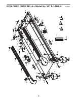
Page 24: ...R0608A 93 17 81 86 51 76 67 28 62 89 3 83 93 6 31 46 25 25 25 25 25 75 75 56 25 71 68 28 18 61 19 44 27 29 55 36 21 42 21 29 60 36 19 42 27 44 19 19 78 50 78 64 4 10 50 41 41 41 41 10 94 97 10 10 74...

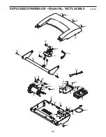
Page 25: ...25 EXPLODED DRAWING B Model No WCTL34308 0 R0608A 34 38 44 79 34 30 59 38 66 90 20 20 20 37 99 65 47 47 47 57 21 21 42 42 21 106 87 2 23 2 72 58 92 82 40 49 21 98 100...

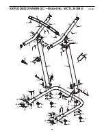
Page 26: ...54 11 53 14 1 9 1 11 14 9 10 48 39 85 26 63 10 63 26 26 63 33 77 22 88 77 24 5 9 2 9 39 70 35 16 63 26 69 69 43 45 32 43 13 105 2 8 5 8 5 2 77 10 10 10 77 63 26 10 10 10 10 35 16 70 69 69 63 26 45 32...

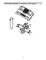
Page 27: ...27 EXPLODED DRAWING D Model No WCTL34308 0 R0608A 15 91 73 4 12 4 4 4 4 4 4 4 4 4...

Page 28: ...ill be responsible for a minimal trip charge This warranty does not extend to any product or damage to a product caused by or attributable to freight damage abuse misuse im proper or abnormal usage or...

Reviews: