background image

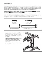
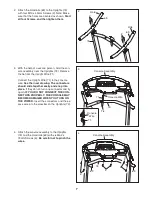
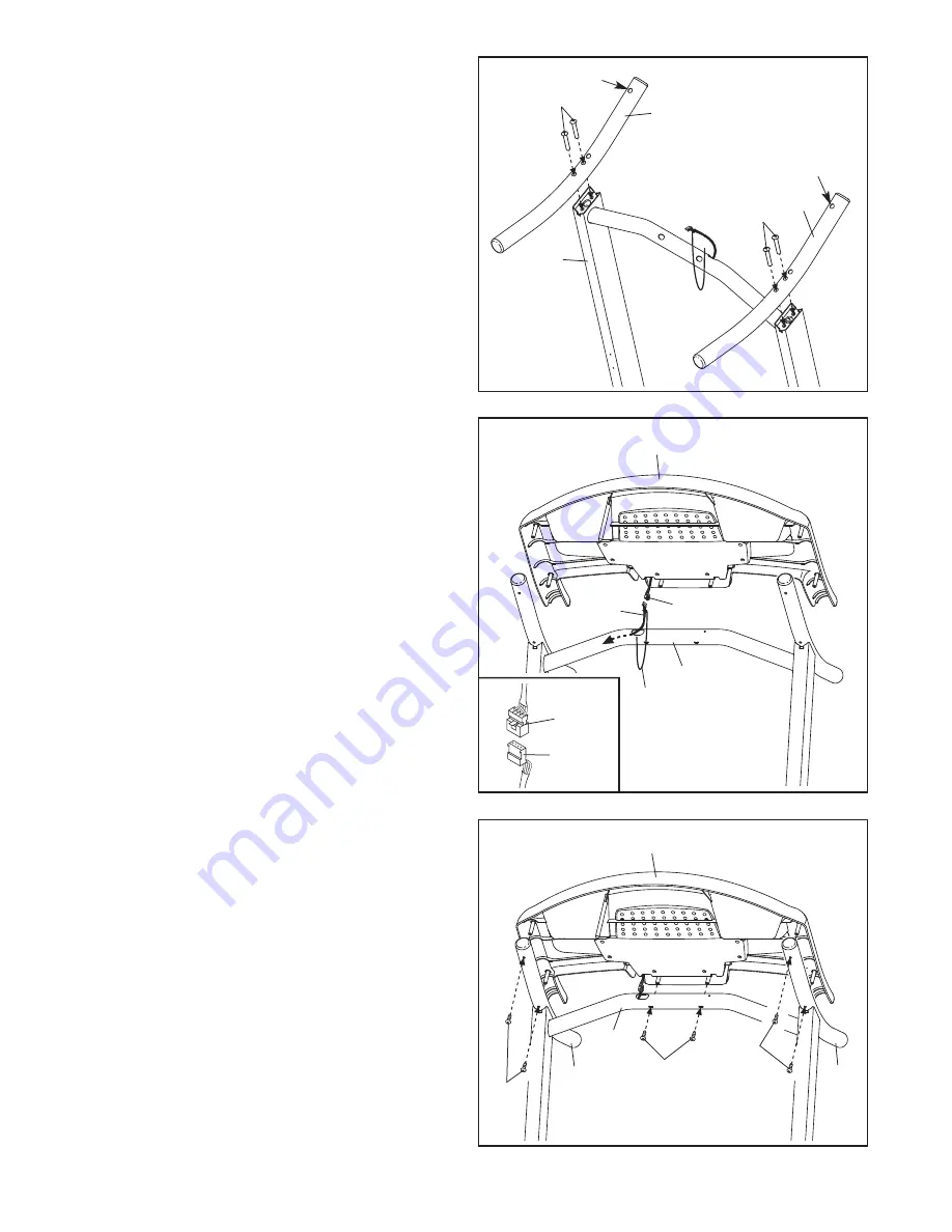
2. Attach the Handrails (69) to the Uprights (73)

with four M10 x 45mm Screws (2). Note: Make

sure that the holes are oriented as shown.

Start

all four Screws, and then tighten them.

3. With the help of a second person, hold the con-

sole assembly near the Uprights (73). Remove

the tie from the Upright Wire (71).

Connect the Upright Wire (71) to the console

wire.

See the inset drawing. The connectors

should slide together easily and snap into

place.

If they do not, turn one connector and try

again.

IF YOU DO NOT CONNECT THE CON-

NECTORS PROPERLY, THE CONSOLE MAY

BECOME DAMAGED WHEN YOU TURN ON

THE POWER.

Insert the connectors and the ex-

cess wire into the crossbar on the Uprights (73).

2

3

71

Console Assembly

Console Wire

73

2

2

73

69

69

71

Tie

Console

Wire

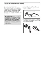
4. Attach the console assembly to the Uprights

(73) and the Handrails (69) with six M4.2 x

19mm Screws (3).

Be careful not to pinch the

wires.

4

3

69

69

3

3

Console Assembly

73

7

Hole

Hole

Summary of Contents for Cadence 21.0 Treadmill

Page 1: ... for reference CAUTION Read all precautions and instruc tions in this manual before using this equipment Save this manual for future reference QUESTIONS If you have questions or if parts are damaged or missing please con tact the store where you pur chased this product Serial Number Decal ...

Page 2: ...IST 20 EXPLODED DRAWING 21 ORDERING REPLACEMENT PARTS Back Cover WESLO is a registered trademark of ICON IP Inc 2 This drawing shows the location s of the warning decal s If a decal is missing or illegible call the telephone number on the front cover of this manual and request a free replacement decal Apply the decal in the location shown Note The decal s may not be shown at actual size WARNING DE...

Page 3: ... a time 10 Wear appropriate exercise clothes when using the treadmill Do not wear loose clothes that could become caught in the treadmill Athletic support clothes are recommended for both men and women Always wear athletic shoes never use the treadmill with bare feet wearing only stockings or in sandals 11 When connecting the power cord see page 9 plug the power cord into an earthed cir cuit No ot...

Page 4: ...by placing objects under the treadmill 23 Inspect and properly tighten all parts of the treadmill regularly 24 Never drop or insert any object into any opening on the treadmill 25 DANGER Always unplug the power cord immediately after use before cleaning the treadmill and before performing the main tenance and adjustment procedures de scribed in this manual Never remove the motor hood unless instru...

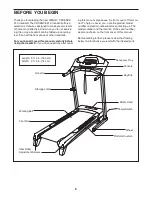
Page 5: ...stions after read ing this manual please see the front cover of this man ual To help us assist you note the product model number and serial number before contacting us The model number and the location of the serial number decal are shown on the front cover of this manual Before reading further please review the drawing below and familiarize yourself with the labeled parts BEFORE YOU BEGIN Handrai...

Page 6: ...te The underside of the treadmill walking belt is coated with high performance lubricant During shipping some lubricant may be transferred to the top of the walking belt or the shipping carton This does not affect treadmill performance If there is lubricant on top of the walking belt simply wipe off the lubricant with a soft cloth and a mild non abrasive cleaner Assembly requires the included hex ...

Page 7: ...drawing The connectors should slide together easily and snap into place If they do not turn one connector and try again IF YOU DO NOT CONNECT THE CON NECTORS PROPERLY THE CONSOLE MAY BECOME DAMAGED WHEN YOU TURN ON THE POWER Insert the connectors and the ex cess wire into the crossbar on the Uprights 73 2 3 71 Console Assembly Console Wire 73 2 2 73 69 69 71 Tie Console Wire 4 Attach the console a...

Page 8: ...set drawing Insert the Spring Clip 86 into the two indicated small holes in the Gas Spring 85 Rotate the Spring Clip until it clips onto the Gas Spring Lower the treadmill See HOW TO LOWER THE TREADMILL FOR USE on page 15 5 83 73 72 6 Identify the rod end of the Gas Spring 85 See the two small inset drawings Locate the Spring Clip 86 in the rod end of the Gas Spring Using your fingernail or a scre...

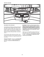
Page 9: ...the indicated end of the power cord into the socket on the treadmill 2 Plug the power cord into an appropriate outlet that is properly installed and earthed in accordance with all local codes and ordinances DANGER Improper connection of the equipment earthing conductor can result in an increased risk of electric shock Check with a qualified electrician or serviceman if you are in doubt as to wheth...

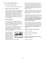
Page 10: ...ve exer cise session To turn on the power see page 11 To use the man ual mode see page 11 To use a preset workout see page 13 To use the information mode see page 14 IMPORTANT If there is a sheet of plastic on the face of the console remove the plastic To prevent damage to the walking platform wear clean ath letic shoes while using the treadmill The first time the treadmill is used observe the ali...

Page 11: ...to a stop Test the clip by carefully taking a few steps backward if the key is not pulled from the console adjust the position of the clip HOW TO USE THE MANUAL MODE 1 Insert the key into the console See HOW TO TURN ON THE POWER at the left 2 Select the manual mode When the key is in serted the manual mode will be selected If you have selected a pre set workout remove the key and then reinsert it ...

Page 12: ...eset the displays press the Stop button re move the key and then reinsert the key 6 Measure your heart rate if desired To measure your heart rate stand on the foot rails and place your thumb on the heart rate moni tor see the drawing on page 10 Do not press too hard or the circulation in your thumb will be restricted and your pulse may not be de tected When your pulse is detected the small heart s...

Page 13: ...flash ing segment indicates the speed setting for the current segment At the end of each segment a series of tones will sound and the next segment of the profile will begin to flash If a new speed and or incline setting is programmed for the next segment the speed and or incline will appear in the display and the treadmill will automatically adjust to the new speed and incline settings The workout...

Page 14: ...ill function normally when you plug in the power cord press the power switch into the reset position and insert the key into the console However when you remove the key the displays will remain lit although the buttons will not function If the demo mode is turned on a d will ap pear in the left display while the information mode is selected To turn on or turn off the demo mode press the Speed decr...

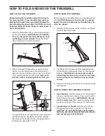
Page 15: ...DMILL Before moving the treadmill fold it as described at the left CAUTION Make sure that the catch is resting against the latch pin Moving the treadmill may re quire two people 1 Hold the frame and one of the handrails and place one foot against a wheel 2 Pull back on the handrail until the treadmill will roll on the wheels and carefully move it to the desired location CAUTION Do not move the tre...

Page 16: ...e sure that the power cord is plugged in If the power cord is plugged in unplug it wait for five minutes and then plug it back in c Remove the key from the console and then reinsert it d If the treadmill still will not run please see the front cover of this manual SYMPTOM The console displays remain lit when you remove the key from the console a The console features a display demo mode de signed t...

Page 17: ...a 3 con ductor 14 gauge 1 mm2 cord that is no longer than 5 ft 1 5 m b If the walking belt is overtightened treadmill perfor mance may decrease and the walking belt may be come damaged Remove the key and UNPLUG THE POWER CORD Using the hex key turn both idler roller screws counterclockwise 1 4 of a turn When the walking belt is properly tightened you should be able to lift each edge of the walking...

Page 18: ...n plug in the power cord insert the key and run the treadmill for a few minutes Repeat until the walking belt is centered b If the walking belt slips when walked on first re move the key and UNPLUG THE POWER CORD Using the hex key turn both idler roller screws clockwise 1 4 of a turn When the walking belt is correctly tightened you should be able to lift each edge of the walking belt 2 to 3 in 5 t...

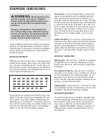
Page 19: ...ur goal is to strengthen your cardiovascular system you must perform aerobic exer cise which is activity that requires large amounts of oxygen for prolonged periods of time For aerobic ex ercise adjust the intensity of your exercise until your heart rate is near the highest number in your training zone WORKOUT GUIDELINES Warming Up Start with 5 to 10 minutes of stretching and light exercise A warm...

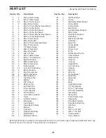
Page 20: ...2 1 Reed Switch 43 1 Reed Switch Clamp 44 1 Magnet 45 1 Drive Belt 46 1 Drive Roller Pulley 47 1 Walking Belt 48 1 Walking Platform 49 1 Right Foot Rail 50 1 Frame 51 1 Right Idler Roller Bracket 52 1 Incline Motor 53 1 Incline Frame 54 1 Idler Roller 55 1 Left Idler Roller Bracket 56 1 Motor Hood 57 1 Drive Motor Bracket 58 1 Drive Motor 59 1 Electronics Bracket 60 1 Controller 61 1 Belly Pan 62 ...

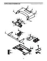
Page 21: ...511A 35 48 50 37 41 13 44 42 41 16 45 46 47 13 36 29 12 3 4 23 12 12 5 5 24 31 5 51 49 40 3 3 40 3 3 10 7 43 5 24 25 26 26 26 26 3 25 3 25 3 25 3 25 3 25 3 25 3 25 29 29 21 14 82 38 54 3 14 55 4 23 12 3 3 25 25 29 21 82 3 30 3 34 76 76 39 3 21 ...

Page 22: ...EXPLODED DRAWING B Model No WATL49710 0 R0511A 19 53 19 94 93 32 32 52 64 87 17 22 29 58 17 15 57 22 56 33 33 33 65 9 9 66 9 9 9 59 11 23 23 11 11 60 61 62 63 88 89 90 11 22 ...

Page 23: ...WING C Model No WATL49710 0 R0511A 76 73 76 79 18 71 1 81 27 28 20 27 28 20 8 8 78 32 78 8 78 79 32 18 8 78 69 68 71 68 69 3 68 75 3 77 77 2 2 68 67 6 6 6 6 74 80 3 3 3 3 1 86 85 91 92 91 92 95 95 70 11 83 72 84 23 ...

Page 24: ...sist you please be prepared to pro vide the following information when contacting us the model number and the serial number of the product see the front cover of this manual the name of the product see the front cover of this manual the key number and description of the replacement part s see the PART LIST and the EXPLODED DRAWING near the end of this manual ...

Reviews: