Project Engineering
54
5.2.3.6 Cascading
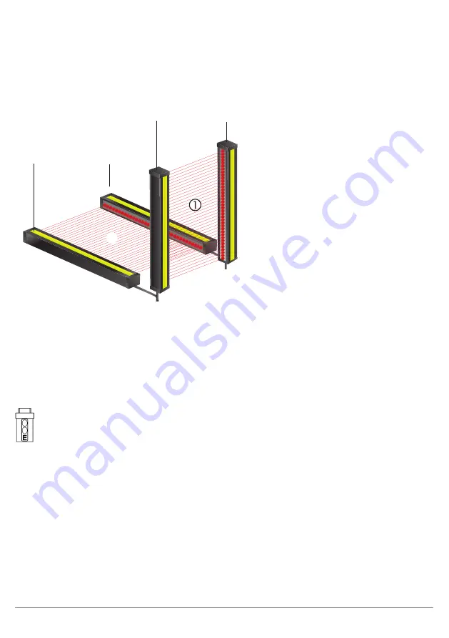
ESPE can be connected so that they all drive a single safety output in order to monitor several safety fields
simultaneously.
Emitter 1 and receiver 1 = master
Emitter 2 and receiver 2 = slave
24 V DC
24 V DC
F-PLC
• The fact that the safety fields of several ESPE drive a shared safety output simplifies the connection to the
machine control.
• Cascaded ESPE demonstrate the same performance characteristics as a single ESPE.
• Cascading can be used to secure adjacent danger zones (e.g. protection against side-stepping).
Note that:
• The cascading is parametrized on the receiver.
• The terms ‘Master’ or ‘Slave’ are used to differentiate between the components:
– Master – component with direct connection to the machine control
– Slave – components with connection to the master
• Every SEFG device can take on the role of the master or the slave.
Conditions:
•
No more than 3 sensors can be cascaded together.
•
The response time is extended by the response time of the upstream receiver with each downstream
receiver.
• If mutual interference between the beam paths is possible, the sensors must be coded (see
.
• Individual settings on an ESPE only apply for the relevant system. But switching off an ESPE always im-
pacts the shared safety output.
•
The function types contactor monitoring and restart inhibit may only be parametrized on the master.


