

English
soldering bits, a Ø 7.0 mm hole must be tapped in the
required position, the push-on nipple must be screwed into it
and the vacuum hose from the FE soldering bits must then
be pushed onto the nipple.
Electrical connection
The nominal voltage must be checked against the details
given on the nameplate prior to commissioning. If the mains
voltage is correct, connect the WFE 20D to the mains supply
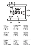
(9) and switch on the equipment using the mains switch (11).
A green LED (filter is OK) indicates that the unit is running.
The percentage details for the turbine rotational speed are
shown on the display (13).
4. Operating the unit
Operating mode
The unit is in
mode 0
when it leaves the factory. Vacuum is
controlled to 8.000 Pa. This is the ideal setting for direct
extraction with WELLER FE soldering irons. Changes are not
possible in
mode 0.
However, if you require a different vacu-
um for control, this can be changed in setting mode 2 from
5.000 Pa to 8.000 Pa in steps of 100 Pa. (Display of 50 – 100)
Switching operating mode
Hold down the
UP
and
DOWN
(14/15) buttons simultaneous-
ly when switching on. The currently set operating mode is
shown in the display (ex works setting -0-). If the
TIMER
but-
ton (16) is additionally pressed, the unit can be switched to
mode 1 or mode 2. When the
UP
and
DOWN
button is
released, the unit starts in the set operating mode. In operat-
ing mode 1, the turbine is speed-controlled. The turbine
speed and thus the extraction power can be adjusted step-
lessly between 20% - 100% using the
UP/DOWN
button
(14/15). Setting mode 2 should only be used for modifying
the control setpoint. The unit should then be switched to
operating mode 0. Operating mode 0 now uses the modified
control setpoint.
Filter checks
The filter status display (17) indicates when (through filter
differential pressure measurement) the permitted degree of
contamination has been exceeded and when the filter insert
has to be changed. The red filter control LED will illuminate
and the unit will be switched off. The sub-micron particle fil-
ter and wide-band gas filter are fitted one on the other, so
that they can be changed together as a compact filter.
The fine dust filter (8) (filter mat), is the pre-filter level of the
compact filter (7) and therefore has to be changed more
often. The pre-filter mat change is satisfactory, if the red LED
(17) is no longer illuminated when the equipment is switched
back on.
Displaying the filter operating hours
Press the
TIMER
button (16) and the current filter operating
hours will be displayed (display X 10). Flashing display. The
operating hours display must be manually reset after a filter
change. Keep the
TIMER
button (16) pressed down until the
display is reset to 000.
Filter operating hours default setting
The filter operating hours can be entered as a default setting
for better handling of the filter change intervals. When the
default operating hours setting has expired, the unit will be
switched off and “filter change required” will be indicated by
a flashing display (13) and the illumination of the red LED
(17).
Press the
TIMER
button (16) to enter the default operating
hours setting. The current filter operating hours will now
flash on the display. Press the
UP/DOWN
buttons (14/15)
simultaneously whilst the display is flashing. Release
UP/DOWN
buttons (14/15) and now use them to enter the
default operating hours.
RS232 Interface
It is possible to control the WFE 20D via a PC using the inte-
grated standard RS232 interface (12). This enables the full
range of system functions to be used or remotely controlled.
Remote control
The remote control (which is available as an accessory) can
be operated via the RS232 interface (12). The unit’s main
functions can be transmitted using this remote control.
●
Switching the unit On/Off
●
Speed setting in mode - 1 -
●
Filter status display
Knowing that the WFE 20D can be operated via a remote
control is helpful when selecting the site for the unit.
Decommissioning
Attention!
A high concentration of pollutants will result in the
active carbon heating up. The equipment should be run
for several minutes in a pollutant free state before being
switched off in order to prevent unwanted heating up.
15
Summary of Contents for Zero-Smog WFE 20D
Page 3: ...WFE 20D...
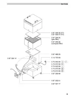
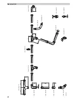
Page 9: ...66 Explo Drawing...


