background image

4

If the button is continuously pressed, the adjustment is fast. Approx. 2 sec. after
releasing the button, the display (2) automatically switches back to showing the actual
temperature. Dependent on the system, when using the hot-air pencil only the set
value is displayed.

Air-setting
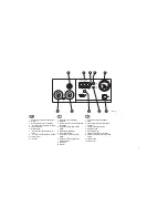
By permanently pressing the „Air“ button (8) the display switches to air-volume. The
air throughput can then be altered gradually from 1 l/min-10 l/min by pressing the
„Up“ or „Down“ buttons (4) (7). If the buttons are continuously pressed, the
adjustment is fast.

Offset / Setback Adjustment (Temperature Compensation / Temperature Reduction)
Switch off unit. Keep „UP“ button pressed during switch on until the self-test has
been completed. Release button. The offset value currently set appears on the display
to the right of the digital point. When the „Air“ button is pressed the display to the left
of the digital point changes to the setback value. These values can be changed using
the „UP“ or „DOWN“ button. 
To save the value set, keep the „AIR“ button pressed until the display flashes.  

Maintenance

When using the hot-air pencil:
Contaminated filters influence the air throughput of the pump. Therefore the main
filters for „vacuum“ (9) and „air“ (10) should be inspected regularly and changed
when necessary. To do this, unscrew the filter cover, remove the contaminated filter
and replace with a new original Weller filter cartridge. Make sure that the filter-cover
seal is correctly in place, insert the compression spring, and screw the filter cover
back on firmly.

When using the desolder:
Desoldering bit, heating element and sensor make up a single unit which is highly
efficient. The desolderer should be cleaned regularly. This involves emptying the
solder collector, changing the glass tube filter and checking the seals. A perfect seal
of the face of the glass cylinder gives full section power. Contaminated filters influence
the air throughput of the pump. Therefore the main filters for „vacuum“ (9) and „air“
(10) should be inspected regularly and changed when necessary. To do this, unscrew
the filter cover, remove the contaminated filter and replace with a new original Weller
filter cartridge. Make sure that the filter cover seal is correctly in place, insert the

compression spring, and screw the filter cover back on firmly. The „vacuum“ filter
removes flux vapours from the extracted air and must therefore be regularly
inspected.

Attention: Working without the filter destroys the vacuum pump.

Use the cleaning tool (0051350099) to clean the suction nozzle opening and the
suction tube.

Various suction nozzles solve many desoldering problems. The suction nozzles can
be changed easily; a suitable tool is integrated into the cleaning tool. The thread on
new suction nozzles should be smeared with „Antilocking paste”. 

Only change suction nozzles when hot.

To avoid the suction nozzle seizing solid with the heat, the suction nozzle should be
unscrewed regularly and the thread smeared with „Antilocking paste”. 

In the case of a very dirty thread or a broken suction nozzle, the repair can be
performed as follows: 

1. Drill out with 4 mmø drill, maximum 11 mm deep. 

2. Recut the thread with an 12 – 24 UNC 2A tap, remove swarf.

3. Smear new suction nozzle with antilocking paste and screw in place.

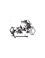
Figures of the cleaning tools, cleaning procedure and exchange of the suction
nozzles see page 20.

3. Information for Operation

Hot-air pencil:
The nozzles are screwed onto the heating element. To change the nozzles use the
socket spanner SW 8 and a wrench.

Attention: The thread length is at most 5 mm. A longer thread destroys the heating
element.

Summary of Contents for WRS 1002

Page 1: ...Weller Operating Instruction Manuel d Utilisation Instrucciones para el Manejo GB F E WRS 1002 10021 10022 ...

Page 2: ...issements 11 Indice Página 1 Descripción 13 Datos técnicos 13 2 Puesta en funcionamiento 13 3 Indicaciones de trabajo 15 4 Indicaciones de seguridad 15 5 Lista de accesorios 15 6 Equipo suministrado 16 7 Precauciones 16 GB F E Table of contents Page 1 Description 3 Specifications 3 2 Installation 3 3 Information for operation 4 4 Safety information 5 5 Accessories 5 6 Scope of delivery 6 7 Warning...

Page 3: ...augmente la valeur réglée 5 Indicateur de dépression 6 Interrupteur général 7 Touche Down réduit la valeur réglée 8 Touche Air pour le réglage de la quantité d air 9 Filtre vide 10 Filtre air 1 Conector hembra para soldador 2 Visor 3 Punto luminoso para control óptico de régula 4 Tecla Up aumenta el valor 5 Display de vacío 6 Interruptor de red 7 Tecla Down disminuye el valor 8 Tecla Air para sele...

Page 4: ...2 11 Mains fuse 5 x 20 12 Mains connection 11 Fusible secteur 5 x 20 12 Connecteur secteur 11 Fusible 12 Conexión a red GB F E 12 11 120V T1 6A 4D9R783 ...

Page 5: ...ntrol solder desolder 150 F 850 F hot air pencil 150 F 1000 F WSP 150 150 F 1000 F Pump duty cycle 30 30 sec max capacity 20 l min hot air 10 l min max vacuum 0 7 bar 2 Installation Place the soldering bit in the safety holder Connect the connecting cable on the control instrument Plug in and latch the electrical connector on the 7 terminal connector 1 For the hot air pencil Push the air hose onto...

Page 6: ...es emptying the solder collector changing the glass tube filter and checking the seals A perfect seal of the face of the glass cylinder gives full section power Contaminated filters influence the air throughput of the pump Therefore the main filters for vacuum 9 and air 10 should be inspected regularly and changed when necessary To do this unscrew the filter cover remove the contaminated filter an...

Page 7: ...e soldering bit should be wetted with solder This removes oxide layers and contamination which might have occurred during storage When pausing between soldering and before putting the soldering iron down ensure that the bit is well tinned Do not use very aggressive flux Attention Never use the soldering iron without a bit as this will damage this heating element and temperature sensor General The ...

Page 8: ...of burn by liquid solder Wear adequate protective clothing to protect yourself against burns 10 Protect your eyes Wear protective goggles Observe especially the warning notes of the adhesives manufacturer when adhesives are processed Protect yourself against tin splashes Danger of burn by liquid solder 11 Use a solder smoke suction device If facilities for the operation of a solder smoke suction d...

Page 9: ...n the operating instructions 21 Warning Please only use the accessories or optional devices which are mentioned in the list of accessories in the operating instructions Use Weller accessories or optional devices on original Weller equipment only The use of other tools and other accessories may cause injuries 22 Please have your soldering equipment repaired by an electric expert only This soldering...

Page 10: ...aque outil de soudage Le boîtier métallique est recouvert d une laque antistatique La panne cuivre de fer à souder est mise à la masse d une manière fixe Données techniques Dimensions L x P x H 240 x 270 x 105 mm Tension secteur 12 20 V 60 Hz Puissance 175 W Classe de sécurité 1 et 3 Fusible 11 T1 6 A 5 x 20 Régulation de la température Fer à souder dessouder 150 F 850 F Stylo à air chaud 150 F 10...

Page 11: ...er les valeurs réglées maintenir la touche AIR enfoncée jusqu au clignotement de l afficheur Maintenance Fontionnement avec le stylo à air chaud Des filtres encrassés influencent le débit d air de la pompe Il faut donc contrôler régulièrement le filtre principal pour vac 9 et air 10 et éventuellement le changer Pour cela dévisser le bouchon de filtre retirer le filtre encrassé et introduire une no...

Page 12: ...e dessoudage la fonction de vide peut être amméliorée d un temps de ralentissement pour la pompe Cette fonction de temps de ralentissement n est pas activée en usine Activation du temps de ralentissement de la pompe Arrêter l appareil Appuyer sur les touches Up et Down lors de la mise en marche et les maintenir appuyées jusqu à la fin de l autovérification 1 apparaît sur l affichage Relâcher les t...

Page 13: ...ujours l outil de soudage que vous n utilisez pas sur son support original Ne placez aucun objet inflammable à proximité de l outil de soudage chaud 3 Faites attention aux influences de l environnement N utilisez pas l outil de soudage dans un milieu humide 4 Protégez vous contre les décharges électriques Evitez tout contact corporel avec des pièces mises à la terre par ex tuyaux éléments de chauf...

Page 14: ...yez attentifs Faites attention à ce que vous faites Travaillez de façon raisonnable N utilisez pas l outil de soudage si vous n êtes pas concentré 20 Contrôlez les endommagements éventuels de l appareil Avant de continuer à utiliser l appareil vérifiez soigneusement le fonctionnement parfait des dispositifs de protection ou des pièces légèrement abîmées Assurezvous que les pièces mobiles fonctionn...

Page 15: ... barniz antiestático La punta del soldador tiene una puesta a tierra dura Datos técnicos Medidas Ancho x Largo x Alto 240 x 270 x 105 mm Tensión de red 12 120 V 60 Hz Potencia 175 W Clase de protección 1 y 3 Fusible 11 T1 6A 5 x 20 Temperatura Soldador Desoldador 150 F 850 F Lápiz de aire caliente 150 F 1000 F WSP 150 150 F 1000 F Bomba Servicio intermitente 30 30 sec máxima cantidad de extracción...

Page 16: ...o se destornilla la tapa del filtro se saca el filtro sucio y se coloca un filtro Weller nuevo Vigile que la posición de la junta de la tapa es correcta coloque el muelle y vuelva a atornillar la tapa del filtro haciendo una ligera presión En funcionamiento con desoldador La cabeza del desoldador la resistencia y el sensor forman una unidad a través de la que se consigue un excelente grado de efec...

Page 17: ...ay aparece un 1 Soltar la tecla Desprogramación del tiempo de funcionamiento suplementario de la bomba Apagar el aparato Dejar pulsadas las teclas Up y Down durante el encendido hasta que la prueba automática se haya completado En el display aparece un OFF Soltar la tecla Soldador Humedecer con estaño las puntas de soldador que se pueden estañar la primera vez que se calientan Esto elimina las cap...

Page 18: ...guro Las herramientas para soldar no utilizadas se deberán guardar en un lugar seco y seguro fuera del alcance de los niños 7 Evite que su soldador se sobrecargue Utilice el soldador sólo con la tensión y la presión o zona de presión indicadas 8 Utilice la herramienta para soldar adecuada No utilice soldadores de poco rendimiento para sus trabajos Utilice su herramienta para soldar sólo para los f...

Page 19: ...star correctamente montadas y cumplir con sus funciones para garantizar un buen funcionamiento del aparato Las piezas y los dispositivos de protección deteriorados deben ser reparados o sustituidos de manera apropiada por un taller especializado si en el manual de instrucciones no dice lo contrario 21 Atención Utilice solamente los accesorios o aparatos adicionales que figuran en la lista de acces...

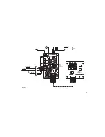
Page 20: ...28 R24 R12 C12 R41 R19 C4 C3 N2 R25 R8 R16 R26 R42 C17 R29 R23 C1 R13 R10 R1 D1 R7 R11 R9 N1 C16 R54 R27 R22 T1 D7 C21 J1 R2 N5 C13 R52 X14 C20 Q1 C5 G1 X6 D10 X11 X12 X13 D9 V1 V2 C14 44 2K 4D9R780 heating element Sensor line voltage 100 C T1 6A 0V 12V 24V pump 7 6 5 4 3 2 1 Display 58740821 X10 T1 T2 T3 S1 S2 S3 X1 D1 R2 D2 D3 R4 R5 R14 R2 R13 R1 R10 R12 R8 R11 R9 R7 C2 A1 ...

Page 21: ...7 408 35 5 87 488 05 5 87 157 20 3St T1 6A 5 70 048 99 5 87 408 21 5 87 488 04 5 87 388 06 5 87 397 07 5 13 318 99 5 13 435 99 5 87 117 18 5 87 117 20 5 13 444 99 5 87 117 18 5 87 408 34 5 13 435 99 5 87 388 14 5 87 177 17 5 87 387 99 5 87 117 22 4D1R779 19 ...

Page 22: ...20 ...
Page 23: ...x 07143 580 108 E mail Info coopertools de Cooper Tools S A S 25 Maurice Chevalier BP 46 77832 Ozoir La Ferriere Tél 01 60 18 55 40 Fax 01 64 40 33 05 Cooper Tools A Division of Cooper Great Britain Limited 4th Floor Pennine House Washington Tyne Wear NE37 1LY Great Britain Tel 0191 419 7700 Fax 0191 417 9421 Cooper Italia S r L Viale Europa 80 20090 Cusago MI Italy Tel 02 90 33 101 Fax 02 90 39 4...

Reviews: