5
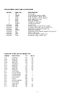
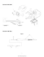
1.2 Check sensor resistance from pin 3 to pin 4 of the tool connector, should measure 1 - 2 ohms.
1.2.1 If sensor resistance is incorrect, remove heater/sensor assembly from handle and check at the
sensor leads (
see PES201 Replacement Heater Instruction Sheet
).
1.2.2 Replace cord/handle assembly if sensor is correct; else replace heater/sensor assembly.
1.2.3 Check resistance from pin 3 to pins 2 and 6 of the tool connector, should measure 1 megohm
minimum.
1.2.4 Remove heater/sensor assembly from handle and check for shorts in wiring inside handle.
Repair or replace as required.
2. Tool overheating.
(NOTE: Tool will overheat with tip removed).
2.1 Check resistance from pin 3 to pin 4 of the tool connector, should measure at least 1- 2 ohms.
2.1.1 Remove heater/sensor assembly and check for shorts in wiring inside handle. Repair wiring as
required, or replace cord/handle assembly. Complete instructions are provided with
replacement part.
3. High voltage on tip.
3.1 Check resistance from pin 5 of the tool connector to tip, should measure 2 ohms maximum.
3.1.1 If tip ground is open, remove heater/sensor assembly and check continuity of ground wire in
cord.
3.1.2 Repair wiring as required, else replace cord/handle assembly if open.
Weller
®
ET and SMT series tips are solid Copper, plated with Iron, Nickel and Chromium. The Nickel and Chromium protect
the shank from corrosion and solder creep. The tips are pre-tinned in the working area with solder. Use only Weller
®
solder-
ing tips. Use of non-Weller
®
components may void product warranty if the non-Weller
®
component causes damage to the
unit. Consult tool and tip selection sheet for available tip styles.
1. Keep tip tinned; wipe only before using.
2. Use rosin or activated rosin fluxes. Acid type fluxes will greatly reduce tip life.
3. Remove tip and clean with suitable cleaner for flux used. The frequency of cleaning will depend on the type of
work and usage. Tips in constant use should be removed and cleaned at least once a week. Corrosion between tip
and sensor can cause erratic temperature control.
WARNING: If tip does not remove easily, do not force it
.
The sensor will be damaged. Try removing the tip while heated. If this does not work, return tool to Weller
®
for
service. When installing new tips, they should slide freely over sensor probe.
4. Dont try to clean tip with abrasive materials and never file the tip. To do so will greatly reduce tip life. Tip wettability
is affected by contact with organics; such as plastic resins, silicone grease, and other chemicals. If the tip be
comes unwettable, it may be cleaned hot with a soft steel or brass brush using solder flux as a solvent; or with a
Weller
®
WPB1 polishing bar (use only when the tip is cold). Do not over do this or the iron plating will be removed
and the tip ruined. Re-tin tip immediately after cleaning to prevent oxidation.
5. Do not remove excess solder from heated tip before storing. The excess solder will prevent oxidation of the wettable
surface when tip is re-heated.
6. Do not use any compound or anti-seize material on Weller
®
tips or sensor probe. This may cause wettability
problems and may cause seizing after extended heating periods.


