WELDPRO MIG155GD Operator'S Manual Download Page 4

Introduction

Thank  you  for  purchasing  the  Weldpro  MIG155GD  welder.    This  welder  is  designed  and  built  using  the  very  best  quality 
components to afford a great welding experience and great performance.
This manual contains the description of the hardware and the operating instructions of the equipment. For your safety and that 
of others, please read this manual carefully.

Attention

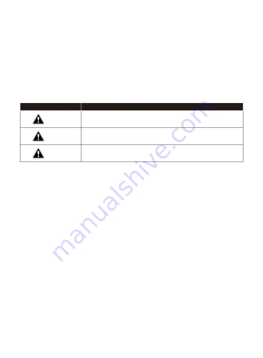
Pay attention to the words following the signs below.

Sign

Description

The  word  following  this  sign  means  that  there  is  great  potential  danger,  which  may 
cause a major accident, damage or even death, if the instructions are not followed.

The word following this sign means that there is some potential danger, which may 
cause bodily injury or property damage, if the instructions are not followed.

The  word  following  this  sign  means  that  there  is  potential  risk,  which  may  cause 
malfunctions and/or breakdowns, if the instructions are not followed.

DANGER

WARNING

ATTENTION

Edition

The contents of this manual are updated regularly in order to include all product updates. The manual is to be used solely as a 
user’s guide, except where indicated otherwise. No warranties of any kind, whether expressed or implied are made in relation to 
the information, descriptions, suggestions or any other content of the manual.

The images of this manual are for reference only. If there is any inconsistency between the image and the actual product, the 
actual product will govern.

3

Summary of Contents for MIG155GD

Page 1: ...MIG155GD Operator s Manual LINLONG LIMITED www weldpro com...

Page 2: ...1 Technical support 651 329 2686 www weldpro com Tel 651 342 1459...

Page 3: ...STOP 2...

Page 4: ...word following this sign means that there is some potential danger which may cause bodily injury or property damage if the instructions are not followed The word following this sign means that there i...

Page 5: ...PRODUCT DESCRIPTION 3 TWO YEAR WARRANTY 4 TECHNICAL PARAMETERS 5 GENERAL WELDING FACTS 6 ELECTRICAL VOLTAGE 7 INSTALLATION 8 OPERATION 9 Daily checking 10 TROUBLESHOOTING 5 16 17 18 19 20 21 22 30 31...

Page 6: ...Weldpro Safety 5 Weldpro Safety...

Page 7: ...ate maintain and repair this equipment A quali ed person is de ned as one who by possession of a recognized degree certi cate or professional standing or who by extensive knowledge training and experi...

Page 8: ...Owner s Manuals industry standards and national state and local codes 2 Arc Welding Hazards Electric shock from welding electrode or wiring can kill Wear dry hole free insulating gloves and body prote...

Page 9: ...out of the fumes Do not breathe the fumes Use enough ventilation exhaust at the arc or both to keep fumes and gases from your breathing zone and the general area The recommended way to determine adequ...

Page 10: ...explosion Use welding helmet with correct shade of lter see Section to choose the correct shade Wear welders cap and safety glasses with side shields Use ear protection when welding out of position o...

Page 11: ...use res Have a re extinguisher nearby and have a trained re watch ready to use it After completion of work inspect area to ensure it is free of sparks glowing embers and ames Do not cut on containers...

Page 12: ...ry free of oil and grease and protected from hot metal and sparks Be sure input ground wire is properly connected to a ground terminal in disconnect box or receptacle Properly install ground and opera...

Page 13: ...ar protection when cutting out of position or in con ned spaces Button shirt collat Wear body protection made from durable ame resistant material leather heavy cotton wool Body protection includes oil...

Page 14: ...and cutting hazards are ampli ed in con ned spaces See ANSI Z49 1 listed in Principal Safety Standards Section 9 Cylinders can explode if damaged Con ned spaces are areas which lack room for full mov...

Page 15: ...nt of adequate capacity to lift and support unit If using lift forks to move unit be sure forks are long enough to extend beyond opposite side of unit Do not place unit where it can easily tip over or...

Page 16: ...will cause radio interference indoor operators shall take fully preventative measures For more information go to www P65Warnings ca gov WARNING Cancer and Reproductive Harm www P65Warnings ca gov For...

Page 17: ...ng PAC Less than 20 20 40 40 60 60 80 80 300 300 400 400 800 4 5 6 8 8 9 10 4 5 6 8 9 12 14 Torch brazing TB 3 or 4 Torch soldering TS 2 Carbon arc welding CAW 14 Plate thickness Mm in Oxyfuel gas wel...

Page 18: ...hort circuit transfer and mixed transfer modes this way it shows better performance than other machines Compared with welding machines using silicone controlled recti er and hot tapping our products h...

Page 19: ...unction by the customer was user error Weldpro may request a shipping fee refund prior to the return of the item to the customer Prior to returning any item thought to be malfunctioning or damaged due...

Page 20: ...ss Insulation class Cooling method Weight lb Dimensions in 22 4x11 6x20 7 35 7 Fan cooled F Ip21 22ga 8ga MIG 023 030 Flux cored 0 30 0 40 1 6 6 39 4 80 0 73 MIG 15 5 20 MMA 21 2 24 4 MIG 15 5 22 MMA...

Page 21: ...ng gas Typically for MIG welding that shielding gas is a mix of Carbon Dioxide CO2 and Argon gas usually in the percentage of 25 CO2 and 75 Argon It is the cleanest smoke free of the three weld types...

Page 22: ...from your welding torch end electrode as it travels in its circuit When welding using either the MIG style or MMA style of welding we want our polarity to be electrode positive With current always tr...

Page 23: ...sed for both MIG which is solid wire with shielding gas and ux cored arc welding Please see below the MIG welding installation diagram In ux cored arc welding mode the gas cylinder does not need to be...

Page 24: ...E WELDING Follow the above procedure except shielding gas is not required nor does it have to be connected to your welder Remember to change the polarity on your welding lead so that the ground clamp...

Page 25: ...y thread it back on being sure not to over tighten it While you have the contact tip off it s a good idea to look at the size marked on the contact tip There are times when it will be marked with Impe...

Page 26: ...e it seated completely you can turn the silver thumb screw to gently snug against your torch cable Note failure to back this torch cable thumb screw out before you install your torch cable into the ma...

Page 27: ...n of the drive assembly to match the size of the wire you will be using and reinstall Do not over tighten the wire tensioner on the drive mechanism Figure 3 example of knurled drive roller Figure 4 ex...

Page 28: ...an always gently tighten your tensioner You are now ready to automatically feed your new reel of welding wire through your torch cable 7 The W Weldpro MIG machines have a special function that auto se...

Page 29: ...and socket tting that does not require Te on tape and should not be used However the small double female brass ttings just above the connection being made does not have a ball and socket tting on its...

Page 30: ...sory and can be purchased separately from WELDPRO 1 Switch the selector switch to the Spool Gun position 2 Open the side door of the welder and loosen the Torch Tensioner located on the side of the dr...

Page 31: ...to the welding wire If this is too tight it will deform the wire and cause feeding issues if it is too loose the drive roller will slip on the wire 8 Remove the nozzle and contact tip 1 Replace the wi...

Page 32: ...ct may be different Front panel 1 Voltage adjustment knob 2 Power indicator light 3 Fault indicator 4 Current adjustment knob 5 MIG welding torch 6 Positive outlet 7 Polarity Reversing Switch 8 Negati...

Page 33: ...O2 0 6 024 0 8 030 0 9 035 0 6 024 0 8 030 0 9 035 0 8 030 0 9 035 15 0 40 15 6 40 15 7 50 16 0 50 16 5 50 16 5 50 16 5 65 16 5 65 17 0 65 17 3 65 17 0 65 17 5 65 15 5 65 18 5 90 17 5 80 18 0 85 19 2...

Page 34: ...s damaged or the O ring is worn down CABLES Component To check Remarks Cable of the welding torch 1 May cause poor wire supply 2 If the cable is bended too much the arc will be unstable Output cable T...

Page 35: ...1 The silicone bridge is broken or the silicon bridge connector is not connected properly 2 The power supply panel is burnt out 3 Check the connections of the cable connecting the power switch with th...

Page 36: ...LINLONG LIMITED www weldpro com...

Reviews: