Spare Parts Overview
115041
47
9.2
Spare parts
– Laboratory-Vacuum-Systems,
unreg manually regulated
Spare parts view LVS 300 Z, unregulated
Fig. 12 Front- and rear unit - LVS unregulated (without item no. 1 and 2)
Page 1: ...ginal manual Laboratory Vacuum Systems Ultimate pressure 8 mbar Models unregulated LVS 300 Z manual regulated LVS 301 Z LVS 302 Z automatic regulated LVS 310 Z LVS 311 Z ecoflex LVS 310 Z ef LVS 310 Z ef extern economic LVS 310 Z en 115041 2017 02 02 ...
Page 2: ...written permission of Co Gardner Denver Thomas GmbH All rights under the copyright laws are expressly reserved by Co Gardner Denver Thomas GmbH We reserve the right to make changes and amendments Gardner Denver Thomas GmbH Am Vogelherd 20 98693 Ilmenau Germany T 49 3677 604 0 F 49 3677 604 131 welch emea gardnerdenver com www welchvacuum com Customer Support 49 3677 604 0 ...
Page 3: ...n 13 3 4 Scope of Delivery 13 3 5 Examples of application 14 3 6 Accessories 16 4 Technical Data 18 4 1 View of device and dimensions 18 4 2 Intake Pressure Pumping Speed Diagram 18 4 3 Device data 19 4 3 1 Laboratory Vacuum Systems 19 4 3 2 Vacuum Controller 521 21 5 Assembly and Installation 22 5 1 Unpacking 22 5 2 Installation and Connection 22 5 3 General instructions 22 5 4 Storage 23 5 5 Scr...
Page 4: ... 2 Assembly 43 7 2 1 3 Test 44 7 2 2 Maintenance of the vacuum controller 44 7 2 3 Maintenance of other components 44 7 3 Maintenance by the Manufacturer 44 7 4 Damage Report 44 8 Troubleshooting 45 9 Spare Parts Overview 46 9 1 Service kit Diaphragm Pump 46 9 2 Spare parts Laboratory Vacuum Systems unregulated manually regulated 47 9 3 Spare parts Laboratory Vacuum Systems automatically regulated...
Page 5: ...rform the work that has to be done The user must authorize the operating personnel to do the work that has to be done The personnel must have read and understood the complete Operating Manual before using the laboratory vacuum systems The Operating Manual must be kept at the place of use and be available to the personnel when required 1 3 Intended Use The laboratory vacuum system may only be opera...
Page 6: ...Electrical equipment of machines Part 1 General requirements DIN EN 61000 6 2 2011 06 DIN EN 61000 6 4 2011 09 Electromagnetic compatibility EMC Part 6 2 Generic standards Immunity for industrial environments Part 6 4 Generic standards Emission standard for industrial environments DIN EN 61010 1 A1 2015 04 Safety requirements for electrical equipment for measurement control and laboratory use Part...
Page 7: ...rvice or maintain the Labo ratory Vacuum System if it is accompanied by a fully completed damage report Precise in formation about the contamination also negative information if necessary and thorough cleaning of the Laboratory Vacuum Systems are legally binding parts of the contract Contaminated Laboratory Vacuum Systems and their individual parts must be disposed of in accordance with the legal ...
Page 8: ...pumping action and can lead to damage Prevent solid particles penetrating into the pump When handling glass vessels pay attention to Only use glass vessels with a plastic coating for splinter protection Only use vessels which are suitable for use with vacuums e g round bottomed flasks We recommend that only glass components supplied by the manufacturer are used Do not use Erlenmeyer flasks Before ...
Page 9: ...o perform this test with a number of loads connected to one LVS Consider the regulations of the guideline 1999 92 EC Explosive gases The diaphragm pumps of the series MPC are certified according to ATEX guidelines 2014 34 EU device category 3 valid for the gas contacting parts interior of the pump Aggressive gases An MPC series diaphragm pump is used for extracting vapours and aggressive gases The...
Page 10: ...All exposed glass components 6 7 are coated with transparent plastic as protection against bursting The emission condenser is supplied with insulation The power switch 12 and the plug for the power cable 11 as well as the membrane pump 10 the PC 13 control lead 14 inert gas 16 and the water valve option 15 are lo cated on the right of the column The LVS types are specially preconfigured according ...
Page 11: ...h the outlet valve The valves are actuated by the gas being pumped A large proportion of fluid in the dia phragm pump minimizes the pumping efficiency Materials of the medium affecting pump parts Component Materials Seal EPDM Screw fitting Connecting elements PP PVDF Valve PEEK Diaphragm Elastomer PTFE layer Vacuum hose PTFE Connection head pump head PTFE with carbon fibre reinforcing electrically...
Page 12: ...xternal vacuum controller for installation in for example laboratory furniture Over the cable to the device the electrical connection is made 1 Built in Vacuum Controller extern 2 Laboratory Vacuum System LVS Electrical Installation Built in Vacuum Controller 521 ef extern K1 Sensor Venting valve on the pump rear panel Controller Coupling plug 5 pole Order no 600052 06 K2 24 V DC Water valve on th...
Page 13: ...1 1 1 1 Diaphragm pump 1 1 1 1 1 1 1 Vacuum controller 521 1 cv 1 cv 1 ef 1 en Emission condenser 1 1 1 1 1 1 Separator 2 1 1 1 1 1 1 Pressure side connection for hose DN 8 1 1 1 1 1 1 1 Frequency changer 1 Special variants additional with Dial gauge analog 1 Clamping ring screw A 10 netvac 1 1 1 1 1 Built in Controller 521 1 3 3 Areas of Application The Laboratory Vacuum Systems is intended for v...
Page 14: ...ssurised run back 7 Water valve WV Fig 3 Example of application LVS manually regulated 1 LVS with vacuum controller and control valve cv 2 Suction line 3 Outgoing air 4 Rotary vaporizer 5 Capable of expan sion up to 4 loads 6 Coolant system un pressurised run back 7 Water valve WV Fig 4 Example of application LVS cv Control valve automatically regulated Not included in the scope of delivery ...
Page 15: ...oolant system un pressurised run back 7 Water valve WV Fig 6 Example of application LVS en economic CAUTION The economic Laboratory Vacuum System LVS en is suitable for slow processes and central laboratory supplies using a large hysteresis 50 mbar When installing the switch interval of the diaphragm pump is to be checked In practical applications the time out must be at least 0 5 minutes The inte...
Page 16: ...5 mm netvac Set BC1 62 Order no 700562 for mounting on wood furniture Set BC2 62 Order no 700562 01 for mounting on sheet metal wall with integrated FFKM Check valve Dosing valve and Hose nozzle Area of application Laboratory Suction connection Hose DN 8 10 Connection thread 1 4 outside Material of valve body Polypropylene PP Dimensions W D H Ø 69 69 82 mm Mounting hole Ø 25 to Ø 35 mm Vacuum Cont...
Page 17: ...de diameters 8 mm Hose nozzle with FKM O Ring DN 10 Order no 710955 Material PP Male thread Inlet fitting DN 16 KF Order no 710116 Material PP Male thread Vacuum hose 10 8x1 Order no 828332 Material PTFE Please state the length you want to order Vacuum hose 18 8x5 Order no 828310 4 Material Rubber red Please state the length you want to order Mains connection cable IEC with plug Type 12 CH Order n...
Page 18: ... View of device and dimensions The main dimensions are identical for all types stated here Fig 7 View of device Model LVS 301 Z dimensions see chapter 4 3 4 2 Intake Pressure Pumping Speed Diagram Fig 8 Intake Pressure Pumping Speed Diagram W H D ...
Page 19: ...y with motor protection switch switch and cable Motor power W 180 Operating mode S 1 Motor Type of protection DIN EN 60529 IP 54 Motor Class of insulation DIN EN 600034 1 F 160 C Type Examination Certificate no WELCH_ATEX_03 01 Designation EX II3G IIC T3 X internal Atm only Dimensions W D H mm 360 310 395 360 310 445 Weight kg 16 1 16 3 16 9 17 8 18 1 Order numbers for in 230 V inclusive mains con...
Page 20: ...e Frequency different data upon customer request V Hz 230 50 60 115 50 60 generally with motor protection switch switch and cable Motor power W 180 Input Frequency changer Apparent power W A 680 4 5 Operating mode S 1 Type of protection motor DIN EN 60529 IP 54 Motor Class of insulation DIN EN 600034 1 F 160 C Type Examination Certificate no WELCH_ATEX_03 01 Designation EX II3G IIC T3 X internal A...
Page 21: ...tion max 15 depends upon the control power W Fuse internal controller 5 A Power pack integrated Operating voltage 90 260 V AC Operating frequency 50 60 Hz Output voltage 24 V DC Output current 1 25 A Output power 100 W Entire unit Protective system IP 20 Working temperature 15 40 C Connections IN OUT RS 232 SUB D plug 9 pole OUT Control line for frequency changer Binder socket 4 pole 0 10 V DC OUT...
Page 22: ...ory Vacuum System to the power supply Check that the connections are properly seated 5 3 General instructions Observe the basic safety instructions when using the LVS The pressure device regulation 2014 68 EU must be observed if devices with an over pressure of 0 5 bar or more are connected The pressures at the intake and exhaust sides of the diaphragm pump at the time it is switched on must corre...
Page 23: ... port valve The pressure values may be increased when doing so The diaphragm pump s maximum tolerance of water va pour pressure can be improved or a cleaning run can be made after finishing work by open ing the gas ballast valve this significantly reduces the pumping speed and ultimate pres sure The vacuum ducts must always be laid sloping downwards so that condensates can flow into the relevant s...
Page 24: ...r an analog voltage is output which controls the speed according to the standard tolerance If the set pressure is not reached the speed is automatically adjusted to the pressure loss If the pressure is actively lowered after the setpoint has been reached for the first time it is lowered still further within a settable timeframe The number of ramps can be set up to a maximum of 3 Each ramp starts w...
Page 25: ...tional the device goes into STOP status when Tank full is signalled 6 5 Calibrating the Pressure Sensor A two point calibration is made with a comparison measurement device Calibration at ambient pressure Calibration at ultimate pressure The diaphragm pump is switched off The diaphragm pump is switched on The venting valve is open The venting valve will be closed The vacuum valve is closed The vac...
Page 26: ... manually with the currently selected setpoint in the solvent table see chapter 6 9 Stops the active mode Cancels the input in the pop up window Jumps back to the main menu from submenus Encoder Meaning Turn to select the operating mode Press to select the setting menu for the corresponding operating mode Turn to select menu items Press to open Change pop up window Turn to change values Press to c...
Page 27: ... V 1 15 P 960 mbar MAIN MENU Manual Automatic Low pressure Configuration Self cleaning VCZ 521 V 1 15 P 960 mbar Configuration language display settings pressure unit calibrate back VCZ 521 V 1 15 P 960 mbar display settings contrast brightness display interval min pressure max pressure back VCZ 521 V 1 15 P 960 mbar Select one of the available languages Select contrast in the display Select brigh...
Page 28: ...c Low pressure Configuration Self cleaning VCZ 521 V 1 15 P 960 mbar Configuration language display settings pressure unit calibrate back VCZ 521 V 1 15 P 960 mbar calibrate Cal Start pressure Cal Low pressure back VCZ 521 V 1 15 P 960 mbar Select measured values for display Selection of the upper pressure value Calibration of the lower pressure value The current value of the comparison measuremen...
Page 29: ...c Low pressure Configuration Self cleaning VCZ 521 V 1 14 P 960 mbar MAIN MENU Manual Automatic Low pressure Configuration Self cleaning VCZ 521 V 1 15 P 960 mbar Selection self cleaning for flushing the pump Process several times in succession possible Starting the pump system All control settings are ignored P min Self cleaning Attention system is aired Start in seconds 5 Cancel with OK Self cle...
Page 30: ...g VC 521 V 1 15 P 960 mbar Parameter for mode Manual Parameter Value Unit start graphic start numeric Setpoint numeric setpoint table hysteresis auto stop time No of pressure ramps VENTILATE on STOP Auto Restart back 123 123 0 0 0 0 0 mbar mbar mbar sec Parameter for mode Manual Parameter Value Unit start graphic start numeric Setpoint numeric setpoint table hysteresis auto stop time No of pressur...
Page 31: ...interfaces 6 7 1 1 Electrical Interfaces Location of interfaces see Figure 6 The device is supplied with 24 V DC X1 Power supply input Spring contact clamp Wago type 236 2 pole Pin no Function Specification Comment 1 GND reverse polarity protected blue 2 Primary power supply 24V DC 10 1 5 A reverse polarity protected orange X7 X9 X2 ...
Page 32: ... type 236 3 pole Pin no Function Specification Comment 1 GND bl 2 SENSOR 1 or PCL input 1 I in approx 10 mA Uthreshold approx 13 V gn 3 Sensor supply Corresponds to the voltage at X1 protected by 200 mA self resetting circuit breaker orange X4 Pressure sensor 1 input Spring contact clamp Wago type 236 4 pole Pin no Function Specification Comment 1 GND blue 2 SENSOR 1 Signal 0 5 V or 0 20 mA Resolu...
Page 33: ...tput bl 2 Output Corresponds to the voltage infeed at X1 pnp max 0 5 A with freewheeling diode orange X7 RS232 to the PC Tub plug connector 10 pin via FB to Sub D plug 9 pin Würth 618009221823 Function Pin at tub plug connector Pin at SUB D Comment RXD 3 2 TXD 5 3 GND 9 5 X8 Analog output 1 Frequency converter pump speed Spring contact clamp Wago type 236 2 pole Pin no Function Specification Comme...
Page 34: ...rried out Switch off the controller Call the flash program Select the processor MB96F348A R Y Select the quartz frequency 4 MHz Select the program file Most Current Version Highest Sequential Number VCZ521_XXX mhx Select the serial interface used Option Set Environment Start the programming with Full Operation Confirm the Box PC Reset with OK Switch on the controller quickly don t forget timeout o...
Page 35: ...ind a switched on controller on COM1 to 20 A COM Port 1 255 can also be defined as a command line parameter VCZ521 EXE 2 select COM2 If a controller cannot be found the program goes into offline mode Here a previously saved curve can be reloaded and printed out Internal wiring of the controller RS 232 port PIN Cable colour Connection on the main board 2 white 16 RS 232 RXD 3 brown 17 RS 232 TXD 5 ...
Page 36: ...perating mode The Pmin button functions the same as without a controller The following menu items can be selected from the menu bar File Measure Settings Calibrate Factory settings 6 8 1 Menu item File File Save settings Saving the Settings dialog settings in a file Load settings Loading the Settings dialog settings from a file Print settings Printing out an image of the Settings dialog on the sta...
Page 37: ...2 Menu item Settings CAUTION Settings not required for the selected operating mode are disabled and grayed out in the display Appropriate error messages are displayed if the data ranges are ex ceeded or if inputs are illogical ...
Page 38: ...nues after power failure or shutdown manual setpoint setpoint Enter a setpoint pressure value between 0 and 1100 mbar manual hysteresis hysteresis Enter a hysteresis value between 0 and 1100 mbar pressure drop ramp num No of pressure ramps Number of possible ramps 1 2 3 P start ramp 1 3 start cycle 1 3 in adjusted pressure value example mbar P lower ramp 1 3 cycle time 1 3 in second absolute T low...
Page 39: ...value has been established If the controller is integrated in a complete system or pump system LVS evacuation and venting take place automatically when the stated buttons are pressed The calculated correction values are displayed and can be stored with save CAUTION Ensure that the set pressure is also present at the sensor Designation Explanation Software WELCH Control 521 Control panel at the con...
Page 40: ...wed not settable present not present read not settable Reading the set values Confirmation of acceptance by signal tone send not settable Transmission of changed values to the controller Confirmation of acceptance by signal tone CAUTION These settings are adapted by the manufacturer to match the supplied configuration The user can change the settings after inputting the password File menu item ...
Page 41: ...rethylene trans C2H2Cl2 751 Diisopropyl ether C6H14O 375 Dioxan C4H8O2 107 DMF C3H7NO 11 Ethanol C2H6O 175 Ethyl acetate C4H8O2 240 Heptane C7H16 120 Hexane C6H14 335 Isopropyl alcohol C3H8O 137 Isoamyl alcohol 3 methyl 1 butanol C5H12O 14 Ethyl methyl keton C4H8O 243 Methanol CH4O 337 Methylene dichloride dichloromethane CH2Cl2 no vacuum Pentane C5H12 no vacuum n propyl alcohol C3H8O 67 Pentachlo...
Page 42: ... parts being possibly contaminated by hazardous substances Wear protective clothing if there is contamination 7 2 1 Maintenance of the diaphragm pump Check the pump daily for unusual running noises and heat building up on the surface of the pump We recommend changing the diaphragm after 10 000 operating hours The user may specify that the exchange be made earlier depending upon the application pro...
Page 43: ...NING Renew defective parts if necessary Wear protective gloves Parts must be renewed at the intervals stated in this Operating Manual or as speci fied by the user internally Do not clean with compressed air 7 2 1 2 Assembly see fig 11 1 Place the pump so that the diaphragm is lying in a horizontal position 2 Use the size 3 pin type face wrench to tighten the pressure disc 8 the diaphragm 7 and the...
Page 44: ...ck that the glass vessels are undamaged and if necessary replace Check rubber gasket of the safety valve at the emission condenser and if necessary re place it 7 3 Maintenance by the Manufacturer Repairs and maintenance going beyond the extent of the work described in chapter 7 2 or reconditioning or modification may only be performed by the manufacturer or authorized workshops WARNING The user sh...
Page 45: ... or exchange Diaphragm defective User or Service workshop Exchange of the diaphragm see chapter 7 2 Valve defective Exchange of the valve see chapter 7 2 Vacuum pump dirty General maintenance leaning Valves dirty Cleaning condensates and foreign objects out of the valves Running noise Vacuum pump dirty User or Service workshop General maintenance cleaning Glass components defective and or leaking ...
Page 46: ...he description quantity serial number and order number CAUTION We are not liable for any damage caused by the installation of any parts not supplied by the manufacturer 9 1 Service kit Diaphragm Pump Designation Order no Service kit 402041 The service kit consists of Designation Piece Order no O Ring ø 12 x 2 5 829217 3 O Ring ø 25 x 2 4 829250 1 Diaphragm 2 400732 Valve 4 400656 ...
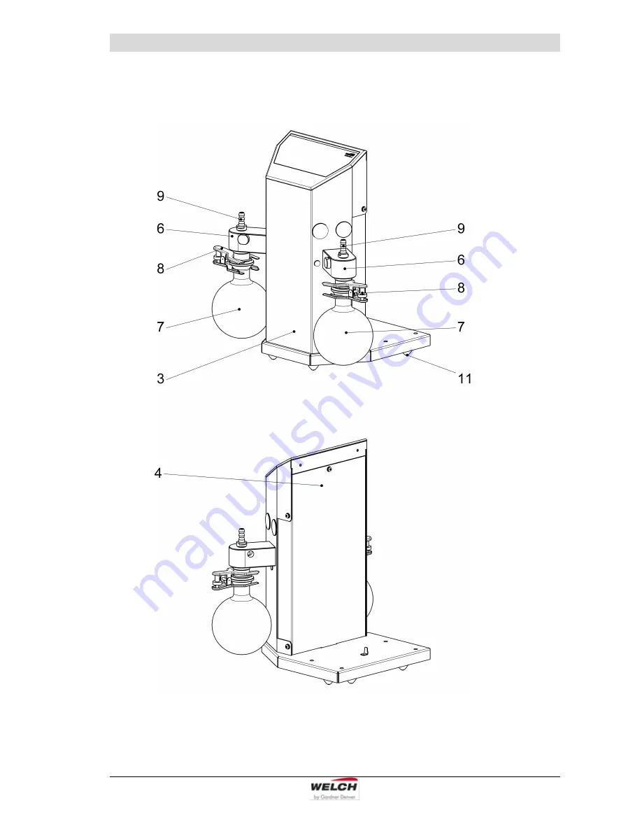
Page 47: ...e Parts Overview 115041 47 9 2 Spare parts Laboratory Vacuum Systems unregulated manually regulated Spare parts view LVS 300 Z unregulated Fig 12 Front and rear unit LVS unregulated without item no 1 and 2 ...
Page 48: ...Spare Parts Overview 48 115041 Spare parts view LVS 302 Z manually regulated Fig 13 Front and rear unit LVS manually regulated without item no 1 and 2 ...
Page 49: ...th seal edge PVDF 10 1 4 2 829931 1 829931 3 Column 1 complete consisting of pos 4 12 1 115502 Column 3 complete consisting of pos 4 12 1 115502 02 4 Rear panel 1 115512 02 115512 02 5 Emission condenser complete KD 500 5 consisting of pos 5a 5k 1 700183 08 5a Intensive cooler with isolation 1 720480 5b Round bottomed flask 500 ml KS 35 1 828839 5c Ball and socket clamp KS 35 1 828845 5d Screw cap...
Page 50: ...Spare Parts Overview 50 115041 Spare parts view LVS 301 Z manually regulated Fig 14 Front and rear unit LVS manually regulated without item no 1 and 2 ...
Page 51: ...502 13 4 Rear panel 1 115512 02 115512 02 115512 02 5 Emission condenser complete KD 500 5 consisting of pos 5a 5k 1 700183 08 700183 08 700183 08 5a Intensive cooler with isolation 1 720480 720480 720480 5b Round bottomed flask 500 ml KS 35 1 828839 828839 828839 5c Ball and socket clamp KS 35 1 828845 828845 828845 5d Screw cap GL 14 2 828872 828872 828872 5e Hose nozzle GL 14 2 828872 1 828872 ...
Page 52: ...Spare Parts Overview 52 115041 9 3 Spare parts Laboratory Vacuum Systems automatically regulated Spare parts view LVS 310 Z Fig 15 Front and rear unit LVS automatically regulated without item no 1 and 2 ...
Page 53: ...Spare Parts Overview 115041 53 Spare parts view LVS 311 Z Fig 16 Front and rear unit LVS automatically regulated without item no 1 and 2 ...
Page 54: ...e round plug flange box 4 pole 2 825277 1 825277 1 4e NT switch power pack 24 V 1 827400 5 827400 5 4f Circuit board 521 1 827429 827429 5 Emission condenser complete KD 500 5 consisting of pos 5a 5k 1 700183 08 700183 08 5a Intensive cooler with isolation 1 720480 720480 5b Round bottomed flask 500 ml KS 35 1 828839 828839 5c Ball and socket clamp KS 35 1 828845 828845 5d Screw cap GL 14 2 828872...
Page 55: ...Spare Parts Overview 115041 55 9 4 Spare parts Laboratory Vacuum Systems ecoflex Spare parts view LVS 310 Z ef Fig 17 Front and rear unit LVS 310 Z ef without item no 1 and 2 ...
Page 56: ...27429 5 Emission condenser complete KD 500 5 consisting of pos 5a 5k 1 700183 08 700183 08 5a Intensive cooler with isolation 1 720480 720480 5b Round bottomed flask 500 ml KS 35 1 828839 828839 5c Ball and socket clamp KS 35 1 828845 828845 5d Screw cap GL 14 2 828872 828872 5e Hose nozzle GL 14 2 828872 1 828872 1 5f Safety valve 1 100838 01 100838 01 5g Vacuum hose PTFE 10 8x1 sold be the meter...
Page 57: ...nd 2 The LVS 310 Z ef extern order no 115244 04 is supplied with a controller which could for example be installed in the rear wall of a laboratory The installation and connection are described in chapter 3 1 4 This eliminates the control panel on the top of the column It is operated from the external controller as described in the chapter 6 ...
Page 58: ...med flask 500 ml KS 35 1 828839 5c Ball and socket clamp KS 35 1 828845 5d Screw cap GL 14 2 828872 5e Hose nozzle GL 14 2 828872 1 5f Safety valve 1 100838 01 5g Vacuum hose PTFE 10 8x1 sold be the meter 0 15 m 828332 5h Screw cap GL 18 2 828876 5j Hose nozzle GL 18 1 828876 1 5k Silicon sealing GL 18 1 828876 2 6 Valve seat complete 1 113522 7 Round bottomed flask 500 ml KS 35 1 828839 8 Ball an...
Page 59: ...Spare Parts Overview 115041 59 9 5 Spare parts Laboratory Vacuum Systems economic Spare parts view LVS 310 Z en Fig 19 Front and rear unit LVS 310 Z en without item no 1 and 2 ...
Page 60: ...e round plug flange box 4 pole 1 825277 1 4e NT switch power pack 24 V 1 827400 5 4f Circuit board 521 1 827429 4g Load relay 1 825741 5 Emission condenser complete KD 500 5 consisting of pos 5a 5k 1 700183 08 5a Intensive cooler with isolation 1 720480 5b Round bottomed flask 500 ml KS 35 1 828839 5c Ball and socket clamp KS 35 1 828845 5d Screw cap GL 14 2 828872 5e Hose nozzle GL 14 2 828872 1 ...
Page 61: ...Spare Parts Overview 115041 61 9 6 Spare parts Diaphragm pumps Spare parts view MPC 301 Z für LVS Fig 20 Exploded view Diaphragm pump ...
Page 62: ...2 400732 11 Tensioning washer 2 400707 400707 400707 400707 12 Pump head 2 400705 02 400705 02 400705 02 400705 02 13 Valve 4 400656 400656 400656 400656 14 O Ring EPDM Ø 25 x 2 4 829250 1 829250 1 829250 1 829250 1 15 PTFE insert 2 400902 400902 400902 400902 16 Connection head 2 410432 410432 410432 410432 17 Distributor 2 1 400903 400903 400903 400903 18 Threaded elbow joint 10 PVDF M12 x 1 3 8...
Page 63: ...briefly The following instructions absolutely must be observed when using these devices Because of the identical construction in principle of the devices of category 2 certified by IBExU notified body these studies relating to the internal space are used for illustration purposes This certification relates to the following device types The certification is a type test per Directive 2014 34 EU It r...
Page 64: ... relating to ambient and gas intake temperatures in the operating instructions are to be observed After maintenance or repair work has been carried out the device concerned must be subjected to an appropriate inspection The final vacuum stated in the documentation and a test on the seal of the internal space of the device are to be checked The tested leak rate may not be under 0 5 x 10 2 mbar x li...
Page 65: ...r ignition temperature on the basis of his knowledge 9 Conformity assessment The conformity assessment for devices of category 3 of device group II and EX II 3G IIC T3 X certification is conducted by the in house Production Inspection in accordance with the specifications set out in the documentation Individual inspections are to be conducted A complete record of the results for every device is to...
Page 66: ...che Geräte für den Einsatz in explosionsgefährdeten Bereichen Teil 1 Grundlagen und Anforderungen Non electrical equipment for use in potentially explosive atmospheres part 1 Basic method and requirements Appareils non électriques destinés à être utilisés en atmosphères explosibles partie 1 prescriptions et méthodologie X DIN EN 13463 5 2011 10 Nicht elektrische Geräte für den Einsatz in explosion...