


15-
Communication
Unit
Value
Standard
IO-Link V1.1
Transmission speed
bit/s
38,400 (COM2)
Min. cycle time
ms
4,0
Max. start time IO-Link
2
ms
280
Max. start time operational readiness
3
ms
750
Table 4: Nominal Electrical Data
5.2.1
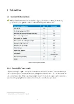
Electrical Interface
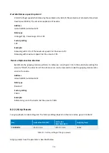
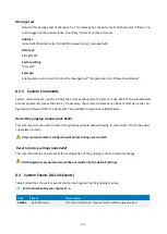
The gripping module has an M8 connector for electrical contact. The pin assignment corresponds to the IO-
Link standard Class A connector. It is shown in Figure 5
Depending on the model, the current consumption of the gripping module exceeds the 200 mA limit
specified in the IO-Link 1.1 standard. It is therefore essential to check whether the IO-Link master
used can permanently supply the rated current specified in Table 4
1
3
2
4
Pin
Strand colour
Signal
Function
1
brown
L+
Power 24 V
2
white
RES
reserved, do not connect
3
blue
L-
Power supply 0 V
4
black
C/Q
IO-Link communication
Figure 5: Pin assignment (view of device connector)
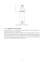
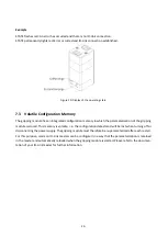
5.3
Name Plate
The type label is located on the transverse side of the gripping module and contains the serial number
and the exact type designation.
2
Time from supply voltage >= 18V to communication readiness via IO-Link
3
Time from supply voltage >= 18V to readiness for operation of the gripping module (without referencing)