Weil-McLain Wgo 3 series Manual Download Page 30

SERVICE TECHNICIAN ONLY — read and follow completely.

Detailed service procedures

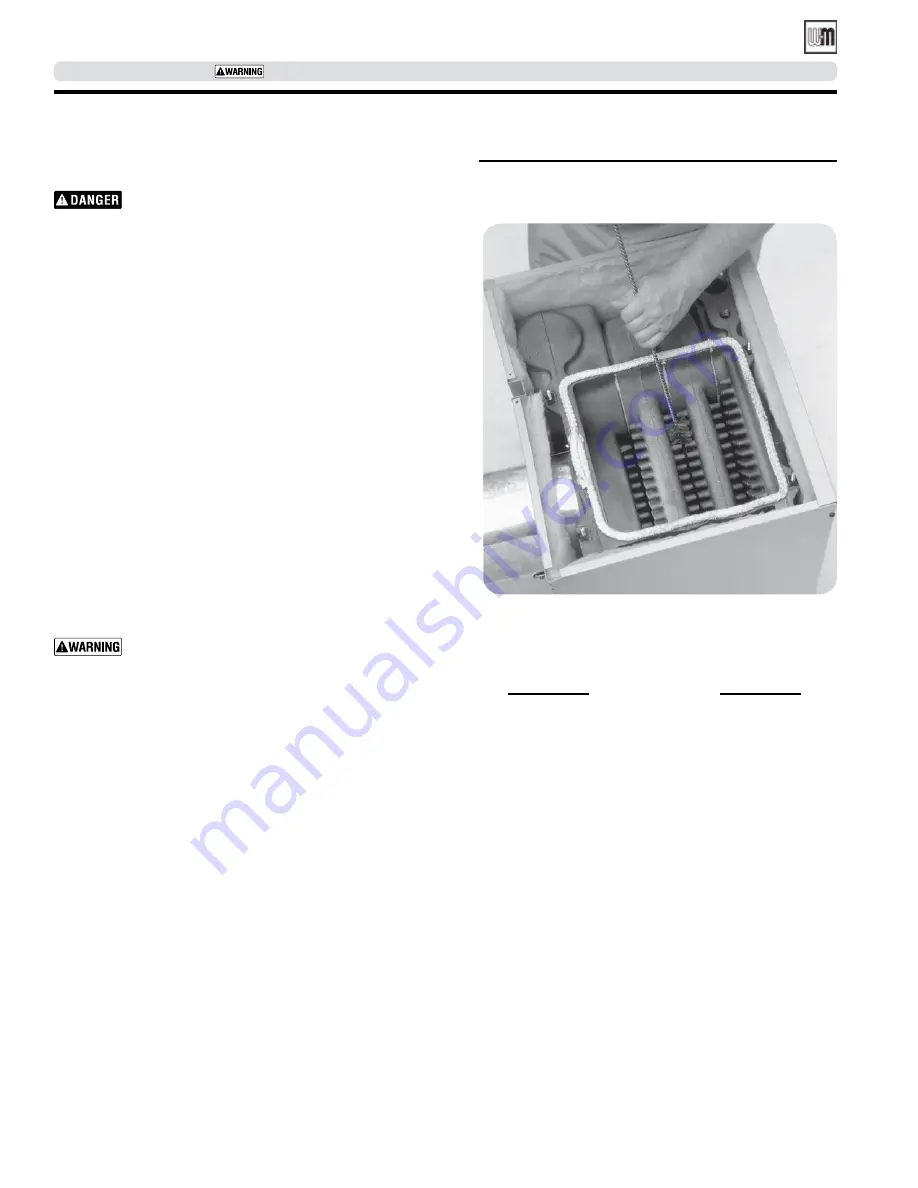
Cleaning boiler flue ways

  Make sure all electrical connections to boiler are turned 

off and wait until boiler is warm, not hot, before clean-

ing. Failure to do so will result in severe personal injury, 

death or substantial property damage.

1.  Top flue boilers

 -remove breeching and jacket top panel.  

Rear flue boilers

 - remove jacket top panel.

2.  Remove flue collector hood, saving hardware for reassembly.
3.  Shut off oil valves. Arrange drip pans under the areas of oil piping 

that will be disconnected. Disconnect oil line at burner so that 

you can swing open the door completely.

4.  Line combustion chamber floor with newspaper to catch any 

soot that will be loosened in the cleaning process.

5.  Starting at the top of the boiler, use a wire flue brush to thor-

oughly clean between all pins at all angles. Be careful not to 

damage side walls of rear refractory.

6.  Move to the bottom of the flue ways and clean up between the 

sections to reach pins left uncleaned in step #5. 

7.  Once the flue ways are cleaned, carefully remove the paper from 

the floor of the combustion chamber.

8.  Verify sealing rope around flue area is intact. Visually check condition 

and position of insulation in combustion chamber floor, and the re-

fractories at the rear of boiler and in the burner mounting door. Replace 

any parts as necessary.

9.  Close burner mounting door and tighten nut securely. Place 

flue collector hood on top of boiler. Secure with hardware from 

step #2.

  Maintain a gas-tight seal to avoid possible flue gas 

leakage and carbon monoxide emissions, which can 

lead to severe personal injury or death.

10. Check breeching for sooting and clean if necessary. Install jacket 

top panel and breeching.

11. Reconnect oil line and all electrical connections.

General description of control operation

Automatic air vent

Air is released when cap is unscrewed one turn.  If air vent leaks, re-

move small cap on top of vent, push in stem of valve and then release 

to clean valve seat. Screw cap completely on, then unscrew one turn.

Temperature limit control

If high boiler water temperature occurs, control shuts down burner, but 

allows circulator to run as long as there is a call for heat. Limit should 

be set higher than temperature needed for the system.
Maximum limit setting is 220°F.

2007 Energy Act Compliance 

In accordance with 

Section 303 of the 2007 Energy Act

, this 

boiler is equipped with a feature that saves energy by reducing 

the boiler water temperature as the heating load decreases. This 

feature is equipped with an override which is provided primarily 

to permit the use of an external energy management system that 

serves the same function.

Figure 24

    Thoroughly clean flue ways between all 

pins at all angles  Start on top of boiler, 

finish from the bottom 

Water relief valve

Provides discharge if boiler pressure exceeds  30 psig. 

Circulator

Circulator provides forced water circulation through boiler 

and piping system.

Pressure-temperature gauge

Provides reading of boiler pressure and temperature.  Maxi-

mum boiler pressure is 50 psig, maximum water temperature 

is 220°F. Temperature will vary according to system and daily 

heating demands. The range will be from room temperature 

up to limit control setting.

The limit control supplied with the boiler must be set-
up with thermal prepurge or thermal targeting active 
unless exempted below:

 IMPORTANT   

THIS OVERRIDE MUST NOT BE USED UNLESS AT 

LEAST ONE OF THE FOLLOWING CONDITIONS IS TRUE:

• 

An external energy management system is installed that reduces 

the boiler water temperature as the heating load decreases.

• 

This boiler is not used for any space heating.

• 

This boiler is part of a modular or multiple boiler system having 

a total input of 300,000 BTU/hr or greater.

• 

This boiler is equipped with a tankless coil (not applicable to 
WGO boilers).

Part number 550-142-331/0421

30

WGO

 OIL-FIRED NATURAL DRAFT WATER BOILER — SERIES 4— 

Boiler Manual

Summary of Contents for Wgo 3 series

Page 1: ...d by a qualified heating installer service technician BEFORE installing read all instructions in this manual and all other information shipped with the boiler Perform steps in the order given Failure...

Page 2: ...ty damage Indicates presence of hazards that can cause severe personal injury death or substantial property damage Indicates presence of hazards that will or can cause minor personal injury or propert...

Page 3: ...Connect breeching 16 General chimney requirements 16 Connect water piping 18 General piping information 18 Install piping 18 DIAPHRAGM expansion tank Figure 11 19 CLOSED expansion tank Figure 12 19 To...

Page 4: ...both immediate and long term effects While the immediate effects of saltwater damage are similar to those of freshwater shorting out of electrical components washing out of critical lubricants etc the...

Page 5: ...ate Check for the following All daily and weekly instructions listed on this page must be fol lowed Burner motor may have to be oiled Some motors are permanently lubricated and do not need additional...

Page 6: ...turned off Fuses or breaker switch tripped Thermostat set below room temperature Fuel valves turned off Not enough oil in tank to supply burner 2 Correct problems found in step 1 If burner does not fi...

Page 7: ...ater logged Have qualified service technician check expansion tank operation Metal flakes found in flue way Contaminated combustion air supply in flue ways Remove sources of hydrocarbons in or near bo...

Page 8: ...und boiler see Figure 2 Jacket cap must be in place on boiler to avoid requiringan 9 minimumclearance from back or top of boiler to combustible material MINIMUM clearances from vent pipe to combustibl...

Page 9: ...pening must freely connect with areas having adequate infiltration from outside Each opening should be at least 140 sq in per 1 GPH input 1 sq in per 1000 Btu input of all fuel burning appliances plus...

Page 10: ...ulation disc must be in place on boilertoavoidrequiringan18 minimumclearance from back of boiler to combustible material 4 Check level Shim legs if needed 5 Check for secure placement of insulation on...

Page 11: ...l boiler Packaged boilers only continued Figure 3 Change from back flue outlet to top flue outlet optional Instructions for Packaged boilers continued on page 15 Part number 550 142 331 0421 11 WGOOIL...

Page 12: ...pen burner mounting door and using utility knife slit floor insulation at joint to be separated 2 Remove 5 draw rod and the longest draw rod from each side Pull block apart Save draw rods nuts washers...

Page 13: ...section near flue collar position sealing rope around top of block with adhesive side to sections Do not stretch rope Make sure rope ends meet Trim excess rope 3 Position flue collector hood on top o...

Page 14: ...cation Size Function B1 1 Return piping B2 1 Alternate return piping for A B WGO C 1 Supply piping E3 Pressure temperature gauge H Drain valve L High limit control N Air vent or expansion tank piping...

Page 15: ...ent of insulation on target wall chamber floor and burner mounting door 3 Securely close door and tighten nut For burners without OEM welded flanges 1 Secureuniversalmountingflangeandgaskettoburnermou...

Page 16: ...ent 9 inches Single wall vent Minimum chimney sizes should be used Oversized chimneys outside masonry chimneys and or derated inputs can result in condensation in chimney Connect breeching Long horizo...

Page 17: ...e bracket One on each side of pipe 0250 056_OVD OVD Damper Required Flue pipe bracket One on each side of pipe Typical location for barometric control Also see control manufacturer s instructions BVSS...

Page 18: ...eliminate potential of severe burns Do not pipe to any area where freezing could oc cur Do not plug valve or place any obstruction in discharge line DIAPHRAGM expansion tank Figure 11 page 19 Make su...

Page 19: ...C tapping N tapping Circulator Alternate circulator location B1 tapping Relief valve Circulator Closed type expansion tank Isolation valve Circulator Automatic air vent Relief valve To diaphragm expan...

Page 20: ...ves to adjust flow to distribute heat to all zones 2 Separate transformer is required to power zone valves Refer to manufacturers installation instruc tions for wiring or contact our Technical Service...

Page 21: ...ed gravity sys tems use piping as shown in Figure 15 or Figure 16 If system piping is plastic without an oxygen barrier a heat exchanger must be used Legend 1 Isolation valve 2 Flow control valve 3 Ci...

Page 22: ...supplied with boiler must be replaced type 105 C wire or equivalent must be used Sup ply wiring to boiler and additional control wiring must be 14 gauge or heavier Provide electrical ground at boiler...

Page 23: ...carton to the burner housing and route the wires to make all connections in burner junction box as shown in boiler wiring diagram High temperature limit To comply withASME UL 726 or Canadian requirem...

Page 24: ...SERVICE TECHNICIAN ONLY read and follow completely Figure 19 Wiring diagram Connect wiring continued Part number 550 142 331 0421 24 WGOOIL FIRED NATURAL DRAFT WATER BOILER SERIES 4 Boiler Manual...

Page 25: ...or death After installing BVSS switch proceed as follows 1 Disconnect power 2 Install Shutoff Switch BVSS Wiring Harness P N 591 391 942 which is included in BVSS kit P N 591 624 650 as follows a Remo...

Page 26: ...the damper to the L2 screw terminal e Connect the green wire from the damper to ground General oil piping requirements Location and installation of oil tanks oil piping and burners must follow NFPA 3...

Page 27: ...of solution will affect sizing of heat distribution units circulator and expansion tank Follow antifreeze manufacturer s instructions Do not add cold water to hot boiler Thermal shock can cause secti...

Page 28: ...es flow adjusted to distribute heat in all zones Thermostat heat anticipator setting if available set properly Refer to Connect wiring page 22 Boiler cycled with thermostat Raise to highest setting an...

Page 29: ...heel make sure blower wheel turns freely oil burner motor if required clean air inlet clean or change fuel filter and strainer 8 Make sure boiler is filled with water 9 Start unit and verify combustio...

Page 30: ...eleased when cap is unscrewed one turn If air vent leaks re move small cap on top of vent push in stem of valve and then release to clean valve seat Screw cap completely on then unscrew one turn Tempe...

Page 31: ...ngs when install ing in confined space Size opening 140 sq in 1000 Btu per 1 GPH input Locate openings near top and bottom of enclosed space Burner adjustments A burner nozzle change may be required r...

Page 32: ...e the following protection 3 thick insulation board over one inch glass fiber or mineral wool batts 2 24 gauge sheet metal with one inch ventilated air space 3 thick insulation board with one inch ven...

Page 33: ...942 381 355 977 381 355 947 Complete Jacket cartons 3 section WGO 2 416 700 460 3 section WGO 3 416 700 461 4 section 416 700 462 5 section 416 700 463 6 section 416 700 464 7 section 416 700 465 8 s...

Page 34: ...ector hood kit for WGO 3 386 700 337 F Collector hood kit for WGO 4 386 700 337 Item Description Part no F Collector hood kit for WGO 5 386 700 338 F Collector hood kit for WGO 6 386 700 339 F Collect...

Page 35: ...ific boiler as indicated in the list below Results from using modified or other manufactured parts will not be covered by warranty and may damage boiler or impair operation Figure 31 WGO Section and f...

Page 36: ...nge 1 Gasket 2 Screws and 2 nuts for sizes 2 3 4 only 381 354 526 Circulator universal hardware kit 11 2 Includes 1 Flange 1 Gasket 2 Screws and 2 nuts for sizes 5 6 only 381 354 531 7 Well 3 4 NPT 4...

Page 37: ...CE TECHNICIAN ONLY read and follow completely Figure 32 WGO Trim part for Series 4 Replacement parts continued Part number 550 142 331 0421 37 WGOOIL FIRED NATURAL DRAFT WATER BOILER SERIES 4 Boiler M...

Page 38: ...8 Left side 14 Approx Figure 33 WGO dimensions inches mm Dimensions BOILER Size B L Inches mm Inches mm WGO 2 10 1 2 266 7 13 3 4 349 2 WGO 3 13 1 2 342 9 16 7 8 428 7 WGO 4 13 5 8 345 9 16 7 8 428 7...

Page 39: ...5 357 295 6 4 257 0 030 25 8 No 1 WGO boiler designed with convertible vertical and horizontal flue outlet 2 MBH refers to thousands of Btu per hour 3 Based on 140 000 Btu gal 4 Based on standard test...

Page 40: ...dust Remove combustion chamber lining or base insula tion from the boiler and place it in a plastic bag for disposal Wash potentially contaminated clothes separately from other clothing Rinse clothes...

Reviews: