background image

General water piping information: 

• System water supply and return piping should

be installed and piping connections attached to
boiler before erecting jacket or installing
controls.

• Do not pipe in through supply and out through

return. This creates reverse water flow through
boiler that must not be used. 

• When three-way valves are used for

temperature modulation, install slow-opening
(minimum 10-minute) valves and boiler
mixing pump to minimize potential of boiler
thermal shock. See W-M Bulletin AE-8402.

Install piping: 

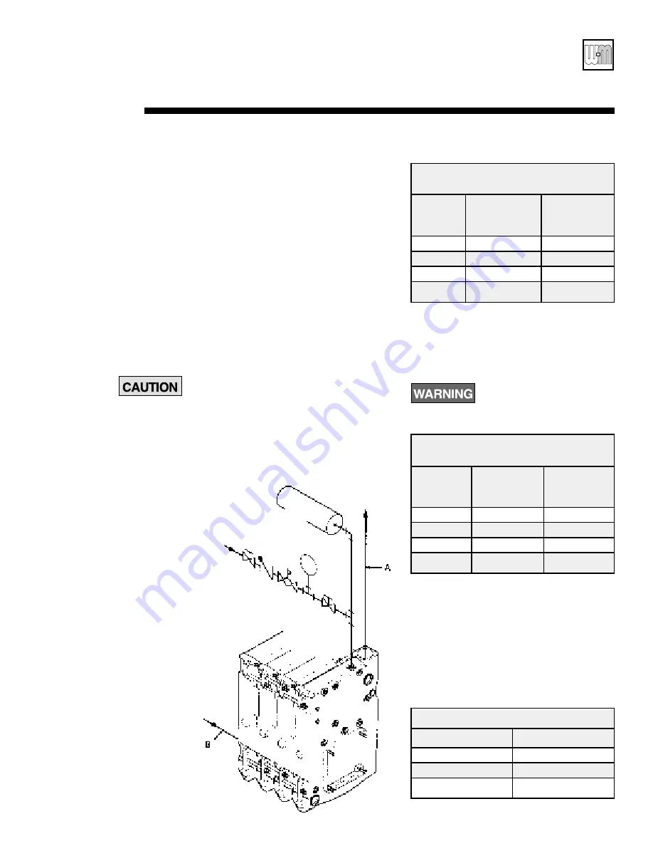
Install piping as shown in Figure 12 below for
single boilers, page 14 for multiple boilers. 

Improperly piped systems or undersized piping
can contribute to erratic boiler operation and
possible boiler or system damage.

1. Connect supply and return piping:

a. Size according to tables below.

1) For 

unknown flow rates,

size piping

per Table below, using 20°F. temperature
rise through boiler.

* All piping sizes based on 20°F. temperature

rise through boiler.

2) For 

known flow rates or higher flow

rate

through boiler, size piping per Table

below. 

Flow at higher velocities than
shown in Table below for pipe
size can damage boiler, causing
substantial property damage.

b. Locate circulator in supply piping.
c. For return piping, use full diameter pipe for

10 times that diameter before making any
reduction. For example, a 4-inch return
should not be reduced any closer to boiler
return tapping than 40 inches.

d. Install system blow-off (drain) valve in

lowest part of return piping close to boiler.
ASME Size requirements are shown in
Table below.

Recommended Minimum Pipe Sizes

for Unknown Flow Rates*

Supply

Return

Boiler

Pipe Size

Pipe Size

Model

A

B

378

2"

2"

478

2-1/2"

2-1/2"

578-678

3"

3"

778-1278

4"

4"

• Installation      • Start-Up      • Maintenance       • Parts

Connect Water Boiler Piping

5a

Part No. 550-141-705

13

Recommended Minimum Pipe Sizes

for Known Flow Rates

Water Supply

Return

Flow Rate

Pipe Size

Pipe Size

GPM

A

B

Up to 35

2"

2"

36 to 50

2-1/2"

2-1/2"

51 to 77

3"

3"

78 to 142

4"

4"

ASME Drain Valve Size

Boiler Model

Valve Size (in.)

378-478

3/4

578-1178

1

1278

1-1/4

Cold

water fill

Expansion

tank

System

supply

(front only)

System return

(front or rear)

Manual

isolation

valve

Manual

isolation

valve

Pressure

reducing

valve

(when used)

Figure 12 Water Boiler Piping

Check

valve

Water

meter

Summary of Contents for 1078

Page 1: ...substantial property damage Part No 550 141 705 0600 78 78 Boiler For Gas Light Oil Gas Light Oil Fired Burners Boiler Manual Installation Start Up Maintenance Parts Installer Leave all documentation received with boiler and burner with unit for future reference User Boiler and burner must be installed and serviced by a qualified service technician ...

Page 2: ... of various risk levels or to important information concerning the life of the product Indicates presence of hazards that will cause severe personal injury death or substantial property damage if ignored Indicates presence of hazards that can cause severe personal injury death or substantial property damage if ignored Indicates presence of hazards that will or can cause minor personal injury death...

Page 3: ...n 12 inches of floor Minimum dimension of each opening 3 inches When all air is taken from within building each opening should be at least one square inch 1 000 Btuh boiler input and freely connect with areas having adequate infiltration from outside When all air is taken from outdoors each opening should connect directly or by ducts from outdoors or crawl or attic spaces that freely connect with ...

Page 4: ...ewall vent pipe 18 inches doublewall vent pipe refer to vent pipe manufacturer s recommendations for vent pipe clearances Lay a foundation if needed Floor construction and condition must be suitable for weight of boiler when filled with water See page 31 for boiler weight water weight A level concrete or brick foundation is required when A floor could possibly become flooded Non level conditions e...

Page 5: ... rollers under steel skid angles to roll boiler 3 Place boiler in final position Center boiler on foundation if used 4 Level boiler Shim under skid angles if necessary 5 Cut off cables Cables are not intended for long term usage Cables may corrode inside boiler weakening their lifting strength Failure to remove cables can result in severe personal injury death or substantial property damage 6 Insp...

Page 6: ...t 1 intervals and push together Do not stretch Do not pre cut rope Gas tight seal must be maintained to prevent possibility of flue gas leakage and carbon monoxide emissions causing severe personal injury or death 3 Remove any grit from port machined surfaces with clean rag Do not use petroleum based cleaning or sealing compounds in boiler system Severe damage to system components can result causi...

Page 7: ......

Page 8: ... Position 1 2 sealing rope in groove Overlap ends at least one inch c Install burner mounting plate Use 1 2 washers and nuts Install observation port assemblies on front and back sections 1 Install front observation port assembly a Apply 1 8 continuous bead of sealing rope adhesive in groove on observation port b Position 3 8 sealing rope in groove Overlap ends at least one inch c Secure assembly ...

Page 9: ......

Page 10: ...assembly See Figure 9 a Lay hood on floor with flanged side up b Wipe flanged surface with clean rag to remove dirt and oil c Apply double faced tape to flanged surface d Apply rope to tape beginning on one side of open end of hood leaving 1 4 extending past edge Around corners bend rope do not cut Do not stretch rope Do not pre cut rope Gas tight seal must be maintained to prevent possible flue g...

Page 11: ...not to distort hood d Tighten six 5 16 x 1 flanged bolts and flanged nuts on flue collar to 30 35 in lbs Overtightening bolts in flue collector hood assembly will cause gasket material to extrude causing possible flue gas leakage and carbon monoxide emissions resulting in severe personal injury or death 4 Check gas tight seal of flue collector hood and flue collar Gas tight seal must be maintained...

Page 12: ......

Page 13: ...g per Table below Flow at higher velocities than shown in Table below for pipe size can damage boiler causing substantial property damage b Locate circulator in supply piping c For return piping use full diameter pipe for 10 times that diameter before making any reduction For example a 4 inch return should not be reduced any closer to boiler return tapping than 40 inches d Install system blow off ...

Page 14: ......

Page 15: ...izer J pipe size b Install system drain valve in lowest part of return piping close to boiler ASME size requirements are shown in Table page 13 c Connect cold water fill piping as shown in Figure 14 Also shown are recommended valves and water meter if used Water meter will detect added makeup water indicating leaks in system Part No 550 141 705 15 Based onASHRAE Handbook recommendations allowing 1...

Page 16: ......

Page 17: ......

Page 18: ......

Page 19: ......

Page 20: ......

Page 21: ......

Page 22: ......

Page 23: ......

Page 24: ... boiler controls 1 Install all wiring in compliance with National Electrical Code ANSI NFPA 70 Any additional national state or local codes 2 Follow burner manual and wiring diagram found in burner information packet 3 Use 14 ga wire for operating and safety circuit wiring 4 Where burner motor voltage differs from control voltage supply proper voltage to each Size fused disconnect s and conductors...

Page 25: ...bustion test equipment to assure proper operation Do not fire boiler without water Sections will overheat damaging boiler and resulting in severe property damage 1 Lock open breeching damper 2 Refer to burner manual for start up and service 3 Let burner advance to high fire Heat boiler to design conditions 4 Using combustion test equipment adjust burner for a 12 1 4 C02 for No 2 fuel oil 0 smoke b...

Page 26: ...atment is needed water boilers only Do not use petroleum based cleaning or sealing compounds in boiler system Severe damage to system components can result causing substantial property damage Continual make up water will reduce boiler life Minerals can build up in sections reducing heat transfer overheating cast iron and causing section failure For unusually hard water areas or low pH conditions l...

Page 27: ... 1 8 8 42 1 2 27 1 2 34 3 8 35 1 2 678 2 4 2 4 2 3 2 3 34 1 8 8 42 1 2 34 1 2 41 3 8 42 1 2 778 2 4 2 4 2 3 2 3 41 1 8 10 41 1 2 41 1 2 48 3 8 49 1 2 878 2 4 2 4 2 3 2 3 48 1 8 10 41 1 2 48 1 2 55 3 8 56 1 2 978 2 4 2 4 2 3 2 3 55 1 8 10 41 1 2 55 1 2 62 3 8 63 1 2 1078 2 4 3 4 2 3 2 3 62 1 8 27 1 8 10 41 1 2 62 1 2 69 3 8 70 1 2 1178 2 4 3 4 2 3 2 3 69 1 8 34 1 8 10 41 1 2 69 1 2 76 3 8 77 1 2 12...

Page 28: ... Gas Light Oil Gas Light Oil Fired Burners Data and Dimensions 15b Part No 550 141 705 28 Front Back Side Intermediate Minimum for heater removal 3 NPT return W Boiler section length 4 NPT supply outlets 3 NPT return Water line ...

Page 29: ... Installation Start Up Maintenance Parts Part No 550 141 705 29 Parts 16a B A C O N E G F D J K L P Q K M P I H ...

Page 30: ...d C 11B340 Flue Collector Hood D 11B341 Flue Collector Hood E 11B351 Flue Collector Hood Hardware Kit includes flat stitched sealing rope 11B342 double faced tape flue collar gasket collector hood gaskets holddown clips hardware K Collector Hood Gasket Kit includes flue collector hood gasket flue 11B311 collar gasket flat stitched sealing rope and double faced tape L Flue Collector Hood End Cap 11...

Page 31: ...l or H for boiler only for use with approved burners Add prefix A to designator for factory assembled 78 ABL 478 Substitute P for B for fire tested package unit PL 478 Substitute S for steam W for water For T intermediate section s and tankless heater s add suffix number required TIH for T intermediate section s with cover plate s only add suffix number required TIP Burner input based on maximum o...

Page 32: ...Part No 550 141 705 0600 32 ...

Reviews: