background image

Specialized Concentrated Focused 

4

Installation 


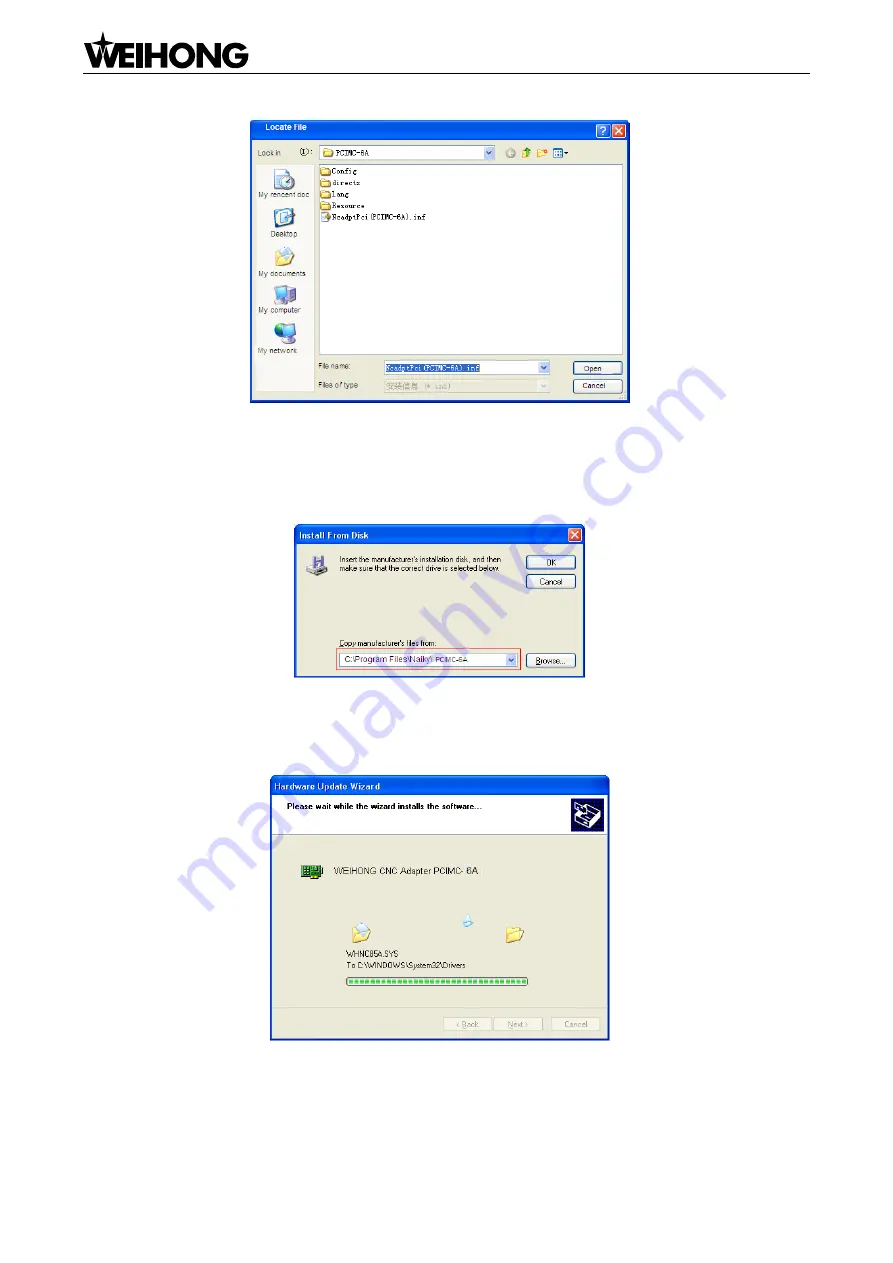
Fig. 2-5 Select the hardware driver 

6)  After hardware driver being correctly chosen, the interface jumps to the previous dialog box where 

the target file directory will be displayed under item 

“Copy manufacturer‟s files from:”, as shown in 

Fig. 2-6. 


Fig. 2-6 Target file directory confirmation 

7)  Click [OK] to go back, and then click [Next] to start updating the driver software. The progressing 

picture is shown as Fig. 2-7. 


Fig. 2-7 Updating the driver 

8)  When the updating is finished, a dialog as shown in Fig. 2-8 will pop up. Click [Finish] to complete 

the update of the hardware driver.   

Summary of Contents for PM53B

Page 1: ...PM53B 53C CNC System Manufacturers Manual 7th Edition Weihong Electronic Technology Co Ltd ...

Page 2: ...ble data or other information contained in this manual may not be reproduced transferred or translated without any prior written permission of Weihong Company The information contained in this manual is constantly being updated You can login to the official website of Weihong Company www en weihong com cn to download the latest PDF edition for free ...

Page 3: ...troduces wiring instruction wiring and machine tool debugging respectively 4 Part 4 appendix including chapter 5 which states the software license agreement Applicable Product Models This manual is applicable to PM53B 53C control card Refer to the table below for details Product Model Remarks PM53B 53C Control Card Self developed high performance motion control card it can be connected with steppi...

Page 4: ...f precautions stipulated in this manual CAUTION general info mainly for informing such as supplementary instructions and conditions to enable a function In case of negligence or omission of this kind of precautions you may not activate a function Note that in some circumstances negligence or omission of even this kind of precautions could cause physical injury or machine damage WARNING warning inf...

Page 5: ...g to the requirements The product should be installed firmly and without vibration During installing casting knocking striking or loading on the product is forbidden To reduce electromagnetic interference power supply components used should be above AC or DC 50V and the space between cable and CNC device should be preserved above 100mm It will be better if CNC device is installed at a position fac...

Page 6: ...and power off It is recommended to power up the machine again at least one 1 minute later after power failure or blackout CAUTION 1 Precautions Related to Product and Manual Matters related to restrictions and functions available stipulated in the manuals issued by the machine manufacturer are prior to those in this manual This manual assumes all the optional functions are available which you must...

Page 7: ...Specialized Concentrated Focused Preface V ...

Page 8: ... 12 3 4 2 Connection to Differential Input Stepping Driver 12 3 5 Wiring Diagram of Terminal Board and Servo Driver 13 3 5 1 Wiring with WISE Servo Driver 13 3 5 2 Wiring with YASKAWA Σ Ⅱ Servo Driver 13 3 5 3 Wiring Diagram of DELTA ASDA_ A AB Servo Driver 14 3 5 4 Wiring Diagram of PANASONIC MINAS_A5 Servo Driver 15 3 5 5 Wiring Diagram of MITSUBISHI MR E Servo Driver 15 3 5 6 Wiring Diagram of ...

Page 9: ...er Setting of PANASONIC MINAS_A4 Servo Driver 21 3 6 6 Parameter Setting of MITSUBISHI MR E Servo Driver 21 3 6 7 Parameter Setting of FUJI FALDIC β Servo Driver 22 3 6 8 Parameter Setting of STONE GS Servo Driver 23 4 Machine Tool Debugging 25 4 1 Debugging Steps 25 4 2 Pulse Test 30 5 Software License Agreement 31 ...

Page 10: ......

Page 11: ...rol Card JP1 DB37M JP2 Gold Fingers Fig 1 1 Structural Drawing of PM53B 53C Motion Control Card See Fig 1 1 PM53B 53C Motion Control Card uses PCI interface The size of PM53B control card is 165mm 120mm The Control Card has 2 sockets JP1 is the DB37M socket for the connection of control signals and connected to the EX23A terminal board with the cable DB37M F JP2 is the socket for Manual Pulse Gene...

Page 12: ...e new hardware device and install its driver automatically 4 Double click the shortcut icon of NcStudio on the desktop if it runs normally installation is over If the control system runs abnormally please check whether the control card is well inserted and whether the gold finger is clean 2 2 Manually Update the Hardware Driver 1 Right click My Computer select Properties and then click Device Mana...

Page 13: ... shown in Fig 2 3 Fig 2 3 Select the driver manually 4 Click Have Disk button to open the next dialog box A dialog box named Install From Disk will pop up as shown in Fig 2 4 Fig 2 4 Select the target file of driver 5 Click Browse to open a dialog box named Locate File as shown in Fig 2 5 select the target hardware driver in the list Choose the target file NcadptPci PCIMC 6A inf under the director...

Page 14: ...y will be displayed under item Copy manufacturer s files from as shown in Fig 2 6 Fig 2 6 Target file directory confirmation 7 Click OK to go back and then click Next to start updating the driver software The progressing picture is shown as Fig 2 7 Fig 2 7 Updating the driver 8 When the updating is finished a dialog as shown in Fig 2 8 will pop up Click Finish to complete the update of the hardwar...

Page 15: ...s customize setup installation package For example when you want to change the settings of some parameters and set them to default value in the process of using NcStudio to achieve the best performance of a machine tool you can change the settings find this tool double click it select a default configuration and generate a new software package with the parameter settings changed ...

Page 16: ... signal one end of the mechanical switch connects to the binary input port and the other end to GND as shown in Fig 3 1 GND IN 24V I O Board Card Fig 3 1 Connection between Mechanical Switch and Binary Input Signal The binary input signal can also be connected with a photoelectric switch or proximity switch of NPN NO or NPN NC type The connection diagram is shown below in Fig 3 2 24V COM IN 24V I ...

Page 17: ...n negative logic The maximum pulse frequency 160KHZ The sketch map of pulse mode is shown below in Fig 3 4 PUL DIR FWD REV L 1 2 3 1 2 3 H Fig 3 4 Type of Pulse Command Output Output mode of differential signal is shown as below in Fig 3 5 VCC XP XP XP Fig 3 5 Output Circuit of Pulse Command 3 2 MPG Interfaces JP2 interface on PM53B motion control card is used for connection with handwheel or MPG ...

Page 18: ...ces Table 1 pin definition of the MPG interfaces Pins No Definition Description 1 5V Power on handwheel 2 HA Encoder phase A signal 3 HB Encoder phase B signal 4 NC 5 NC 6 HX1 X1 override 7 HX10 X10 override 8 HX100 X100 override 9 HSU Selection of the fourth axis 10 HSA Selection of the fifth axis 11 GND Digital ground 12 HSB Selection of the sixth axis 13 HSZ Selection of Z axis 14 HSY Selection...

Page 19: ... 0 ZD ZD ZP ZP 5V X axis Driver Interface COM START CUT STOP ESTOP Power Status Indicator OIL GREEN RED YD YD YP YP 5V Y axis Driver Interface Y axis Driver XD XD XP XP 5V Z axis Driver Interface X axis Driver Operation Inputs GND Cycle Stop Cycle Start Tool Sensor Signal E stop Home Inputs GND Home Y Home X Analog Output Analog Voltage Analog GND 24VDC Power Input PM53B 53C Motion Control Card Sp...

Page 20: ...g GND Forward Rotation Digital GND 24V Power Input PM53B 53C Motion Control Card GND ESTOP Cycle Stop Cycle Start Tool Sensor Signal E stop Z2D Z2D Z2P Z2P Z2 axis Driver Interface Z3D Z3D Z3P Z3P Z3 axis Driver Interface Z4D Z4D Z4P Z4P Z4 axis Driver Interface Y1D Y1D Y1P Y1P Y1 axis Driver Interface Y2D Y2D Y2P Y2P Y2 axis Driver Interface X1D X1D X1P X1P X1 axis Driver Interface X2D X2D X2P X2...

Page 21: ...signal of Z axis Binary input active low connected to Z axis home switch Y0 Reference point signal of Y axis Binary input active low connected to Y axis home switch X0 Reference point signal of X axis Binary input active low connected to X axis home switch GREEN Green working light signal Green light on when machine works normally RED Red alarm light signal Red light on when system E stop occurs o...

Page 22: ...D ZP ZD ZP 5V Y axis Stepping Driver YD YP YD YP 5V X axis Stepping Driver XD XP XD XP 5V EX23A COM DIR CP OPTO COM DIR CP OPTO COM DIR CP 3 4 2 Connection to Differential Input Stepping Driver Z axis Stepping Driver ZD ZP ZD ZP 5V Y axis Stepping Driver X axis Stepping Driver EX23A D D P YD YP YD YP 5V P XD XP XD XP 5V Note TwistedPairfor DifferentialSignals CP D D P P D D P P ...

Page 23: ...ake Line Black 30 BRK OFF 24V COM WiseServoDriver EX23A D P P D 5V Note TwistedPairforDifferentialSignals 40 SRV ON CAUTION Wirings of X Y and Z axis are the same except that two Z axis brake lines can connect to relay to control brakes 3 5 2 Wiring with YASKAWA Σ Ⅱ Servo Driver 12 SIGN 11 SIGN 8 PULS 7 PULS 47 VIN 1 SG 29 S RDY Z axis Brake Red Z axis Brake Black 30 S RDY 24V COM YASKAWA ⅡServoDr...

Page 24: ... 36 SIGN 43 PULSE 41 PULSE 11 COM 45 COM 1 DO4 Z axis Brake Line Red Z axis Brake Line Black 26 DO4 24V COM DELTA ASDA_A ServoDriver EX23A D P P D 5V 37 SIGN 36 SIGN 43 PULSE 41 PULSE 11 COM 45 COM 1 DO4 Z axis Brake Line Red Z axis Brake Line Black 26 DO4 24V COM DELTA ASDA_A ServoDriver EX23A D P P D 5V CAUTION Wirings of X Y and Z axis are the same except that two Z axis brake lines can connect...

Page 25: ... PULS2 46 SIGN1 47 SIGN2 7 COM 41 COM 29 SRV ON 13 GND 11 BRKOFF 10 BRKOFF 50 FG EX23A CAUTION Wirings of X Y and Z axis are the same except that two Z axis brake lines can connect to relay to control brakes 3 5 5 Wiring Diagram of MITSUBISHI MR E Servo Driver 24 NG 25 NP 23 PP 22 PG 1 VIN 13 SG 12 MBR Z axis Brake Line Red Z axis Brake Line Black 13 SG 24V COM MITSUBISHI MR E Servo Driver D 5V P ...

Page 26: ...COM FUJI FALDIC β Servo Driver D 5V P P D EX23A CAUTION Wirings of X axis Y axis and Z axis are the same and the brake of Z axis is internally controlled 3 5 7 Wiring Diagram of STONE GS Servo Driver Z axis Brake Line Black Z axis Brake Line Red 5 BRAKE 28 Sign 13 Sign 27 Pulse 12 Pulse 21 BRAKE STONE GS Servo Driver D 5V P P D EX23A CAUTION Wirings of X Y and Z axis are the same except that two Z...

Page 27: ...r010 10000 5000 2 1 Pr010 Denominator of command pulse frequency division multiplication To be calculate d Pr100 1st position loop gain 480 default Unit 0 1 s Set it according to the actual situation Pr101 1st velocity loop gain 270 default Unit 0 1Hz Set it according to the actual situation Pr102 1st velocity loop integrated time constant 210 default Unit 0 1ms Set it according to the actual situ...

Page 28: ...ng control system the correct quantity of pulse sent by control card is detected by pulse inspection in order to determine whether there is electrical interference Pn000 Direction selection Control method selection 0010 Bit 0 Set 0 CCW is forward rotation viewed from the load end of screw ball Set 1 the rotation direction of the motor is reversed Bit 1 Set 1 position control mode calculate pulse i...

Page 29: ...correct quantity of pulse sent by control card is detected by pulse inspection to determine if there is electrical interference P1 00 External pulse input type ZYX 102 X 2 pulse direction Z 1 negative logic P1 01 Set control mode ZYX1X0 0000 Z 0 when switching control mode DIO is maintaining the set value Since switching control mode is not used Z 0 Y 0 forward rotation anticlockwise from the poin...

Page 30: ...nticlockwise from the view of load Y 1 the rotation direction is reversed X1X0 00 position control mode P1 32 Motor stop mode YX 00 Y 0 when there is no servo enabled motor dynamic brake occurs Y 1 motor is free X 0 motor stops instantly X 1 motor stops with deceleration P1 44 Numerator of Electronic Gear Ratio N1 1 32767 To be calculated N1 M encoder pulses 4 pulse equivalent mechanical decelerat...

Page 31: ...erator of the first pulse command frequency multiplication To be calculated Range 1 10000 Typical values pitch 5 mm encoder resolution 10000 deceleration ratio 1 1 pulse equivalent 0 001 mm Pr48 10000 Pr4B pitch 5mm pulse equivalent 0 001mm 5000 Pr48 Pr4B 10000 5000 2 1 Pr4B Denominator of the command pulse frequency multiplication To be calculated Range 1 10000 3 6 6 Parameter Setting of MITSUBIS...

Page 32: ...form pulse train sign negative logic 41 DIA Signal input SON ON LSP ON and LSN ON automatically selection 0110 Bit 0 Servo ON selection 0 servo on by external input 1 servo on all the time inside Bit 1 last signal of positive rotation range LSP 1 auto servo on inside and no need of external wiring Bit 3 last signal of negative rotation range LSN 1 auto servo on inside and no need of external wirin...

Page 33: ...1 is distributed as b contact point of alarming detection 27 Parameter write protecti on 0 or 1 Set 0 write enable Set 1 write protected 3 6 8 Parameter Setting of STONE GS Servo Driver Para No Parameter Name Value Description F0f Numerator of Electronic Gear Ratio 2 Electronic gear ratio of position mode 4 pulse frequency fed back by servo encoder command pulse frequency F0f F10 Value of F0f F10 ...

Page 34: ...Speed Running Mode Torque Mode Torque Mode CN2 24 Interface Status OFF Mode One Position Pulse Mode Position Pulse Mode Position Pulse Mode Internal Speed Running Mode Internal Speed Running Mode External Speed Running Mode F2e Pulse input mode selection 2 Command pulse string mode selection of position mode 6 quadrature pulse negative logic 1 single pulse string positive logic direction pulse 12 ...

Page 35: ...ameters like max and min operating frequency and source of external command Check wirings and inverter parameters Spindle rotates in the right direction and runs at speed according to the setting value Set relative parameters of servo driver Set pulse equivalent in manufacturer parameters of NcStudio Manually move machine tool to confirm the correctness of directions of each axis Verify the settin...

Page 36: ...d are normally open LEDs should be usually out and by artificially touching a switch the LED should become light which shows the REF point signals have been sent to the terminal board The same method can be taken to test other input ports to ensure the correctness of the wiring between the terminal board and the machine tool to greatly shorten the debugging time 2 Power on the computer and run NcS...

Page 37: ...cuitry and signals polarity If electrical circuitry is correct alter the corresponding signal polarity to ensure the dots in front of the above mentioned signals red 5 Test whether the inputs and outputs on the terminal board work normally For an input the method is as following short circuit an input and COM on the terminal board if the corresponding LED on the terminal board turns on but the cor...

Page 38: ...s not rotate please examine the connection of the inverter Adjust the spindle speed in the software and the actual spindle speed should be changed correspondingly otherwise examine the connection and the parameters setting of the inverter If the spindle rotates in a wrong direction change the connection between the spindle and inverter usually there are three wires connected with the spindle Excha...

Page 39: ...in the manufacturer parameters according to the actual size of the machine tool to enable software limit function The password of manufacturer parameter is ncstudio 11 Set Back to Machine Zero parameter in manufacturer parameters according to the installation position of home switches of the three axes After correct setting perform the Back to Machine Zero function under the menu Operate At first ...

Page 40: ...ping motor frication of machine assembly and endurance capacity of mechanical components limit the maximum speed of the three axes in actual using by modifying the max speed of each axis in manufacturer parameters 15 Set the parameter of auto lubrication set a value smaller such as once every 5 seconds Observe if auto lubrication is executed correctly If so set it according to the actual need If t...

Page 41: ... to the third party or destroy all the copies un transferred 5 You can use the Software Product on a network server or intranet server only if it is stipulated in explicit terms that you are allowed to use the Software Product on a network server or intranet server or you have purchased license for each node and terminal using the Software Product 6 You may NOT sublicense assign or transfer the li...

Page 42: ...e for the commerciality and applicability of special application aim Whether you follow other terms in this agreement or not Weihong Company as well as its agents and sales staff will not be responsible for any profits loss availability loss business break off or any forms of indirect special accidental or inevitable damage or claim made by any third party generated from the using of the Software ...

Reviews: