1
Operating instructions
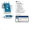
When using the master tester, connect the
end of the cable to be tested (RJ/USB) with
the „TX“ mark and the other cable end with the
„RX“ mark or with the remote terminator RJ/
USB connection.
Turn the power switch to „Test“. The LEDs for
pin 1 light up in „step-by-step“ mode. After op-
erating the „Test“ switch, the LEDs illuminate
one after the other.
In the „Auto“ scan mode, the upper row of
LEDs light, one after the other from pin 1 to
pin 8.
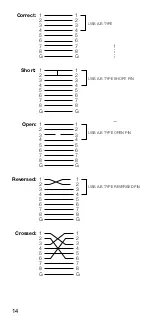
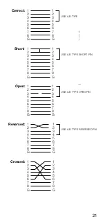
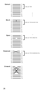
The results on the LED show the exact status
of the cable being tested. If a false LED se-
quence is displayed then the tested cable has
a short circuit, a break, false wiring or a false
connection.
NOTE
When the battery is weak, the LED
is faint or not lit up. This can lead to
false test results.
Remote:
When using the master tester, connect the
end of the cable to be tested with the socket
marked „TX“. Connect the other end of the ca-
ble in the input on the remote terminator. Set
the power switch to the „Auto“ mode. If the ca-
ble terminates in a panel or wall plate then
make use of the adapter cable.
The LEDs on the remote terminator light up
one after the other, depending on the cable
layout detected by the master tester.
1
2
3
1
2


