FreeCon Active PROFINET-POF-Repeater
IE-CDR-V14MSCPOF/VAPM-C
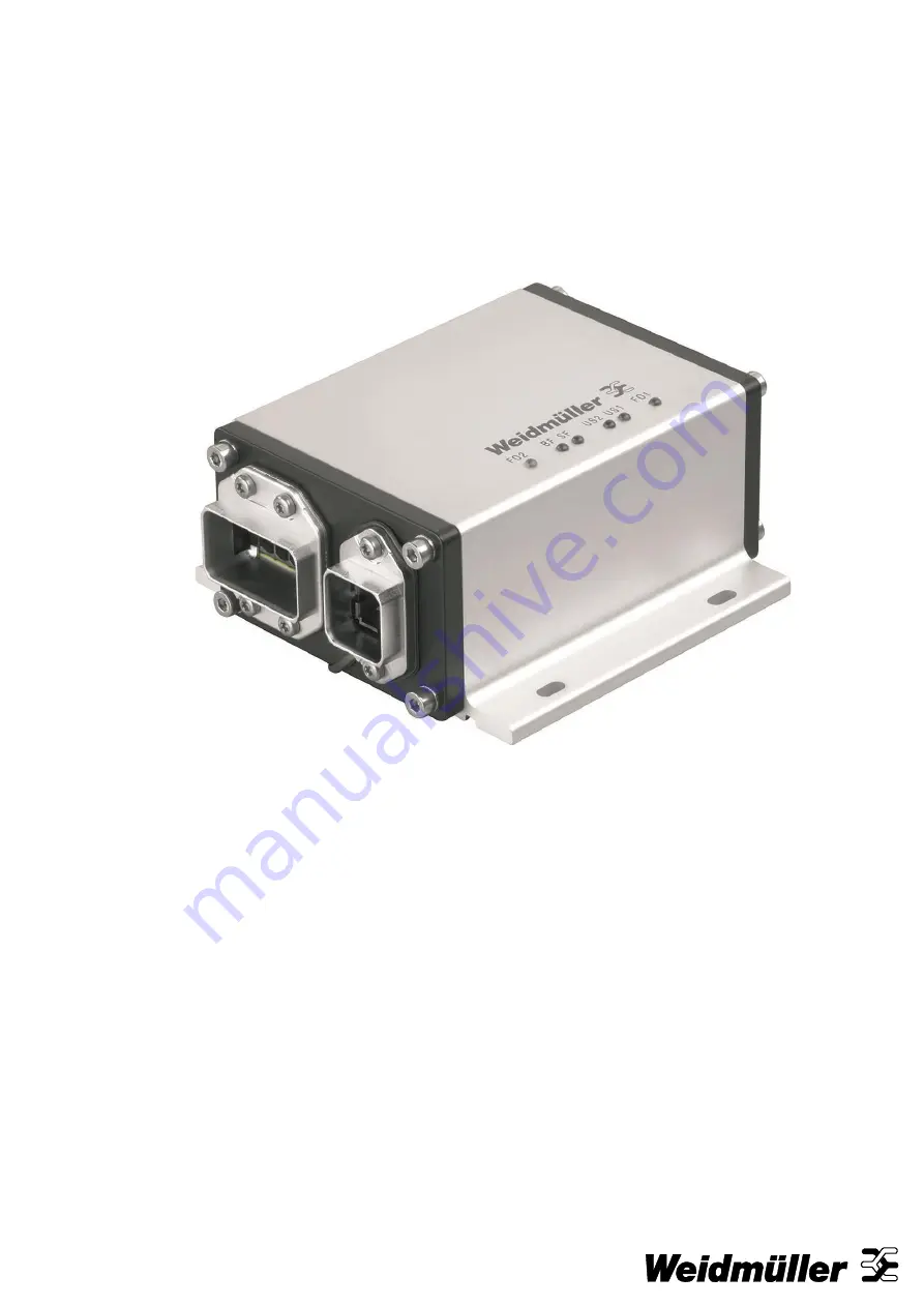
Page 1: ...FreeCon Active PROFINET POF Repeater IE CDR V14MSCPOF VAPM C...
Page 2: ......
Page 3: ...h IP65 metal housing is perfectly suited for harsh robotics applications Revision history Version Date Changes 1 2 Third edition Contact address Weidm ller Interface GmbH Co KG Postfach 3030 32720 Det...
Page 4: ...ive Repeater 8 2 1 Electrical Characteristics 9 2 2 Internals 9 2 3 Mechanical Characteristics 9 3 Installation and Connectors 10 3 1 Mounting 10 3 2 Power connection 11 3 3 Data connection 11 3 4 Gro...
Page 5: ...tended Diagnostic Capabilities 19 5 1 PLC diagnostics 19 5 2 Web browser diagnostics 23 6 Status and Maintenance 24 6 1 LED indicators 24 7 Technical Specifications 26 8 Warranty 28 Appendix A Pin ass...
Page 6: ...e operating instructions have been written for trained and qualified personnel who are familiar with the valid regulations and standards applicable to the field of application 1 3 Accuracy of the tech...
Page 7: ...electrical equipment must not be dis posed through the normal waste disposal channels Electrical equipment must then be dis posed of and recycled separately All devices that fall under the directive m...
Page 8: ...to swap out robotics cabling at the proper time Extends the allowed fibre optic segment lengths by refreshing the fibre optic signal The device is connected in line with the power and fibre optic cabl...
Page 9: ...6 A on either US1 or US2 at 40 C see chapter 3 2 power connection 2 2 Internal CPU The FreeCon Active PROFINET POF Repeater is equipped with an ERTEC 200 processor It runs the VxWorks operating system...
Page 10: ...o the illustrations below for the actual mounting dimensions Four screws must be used to mount the FreeCon Active PROFINET POF Repeater to a wall Use the device itself as a guide to mark the proper lo...
Page 11: ...d in a single ca bling channel together with the power cabling The cabling should be implemented in accordance with the PROFINET Installation Guideline for Cabling and Assembly We recommend labelling...
Page 12: ...t of device II and the Rx receive port of device I to the Tx transmit port of device II as shown in the illustration below Rx Tx Rx Tx DEVICE 1 REPEATER DEVICE 2 Tx Rx Tx Rx Figure 5 Rx to Tx cabling...
Page 13: ...DML file The FreeCon Active PROFINET POF Repeater is normally installed within a facility by integrating its GSDML file in the PLC configuration The GSDML file and a BMP icon of the repeater are archi...
Page 14: ...run this utility 1 Connect the PushPull power connector to the power port of the FreeCon Active PROFINET POF Repeater 2 Connect the PushPull data connector to the data port of the FreeCon Active PROFI...
Page 15: ...Setup and Network Configuration 1253240000 00 02 11 15 Figure 9 Configuring a new IP address in FreeCon CFG...
Page 16: ...g the assigned IP address Use a web browser installed on a PC that is on the same subnet The web interface can be used to manually display the device proper ties firmware version serial number and MAC...
Page 17: ...hcfg cfg You can change parameters like IP address and subnet mask with a standard editor and then upload the new file to the repeater This kind of configuration is usable for batch application 4 6 Di...
Page 18: ...only a few seconds then follows a check and the update of the repeater which needs up to 2 minutes During this update process only the LEDs US1 and US2 glow Never interrupt the power supply during the...
Page 19: ...ting to the FreeCon Active PROFINET POF Repeater s web server 5 1 PLC integration The diagnostic information can be handled by PROFINET PLCs The following description is exemplary for the integration...
Page 20: ...stic Capabilities 20 1253240000 00 02 11 Figure 14 Projecting PROFINET devices The next step ist to set the IP address and device names to make them addressable in the PROFINET network Figure 15 Setti...
Page 21: ...d Diagnostic Capabilities 1253240000 00 02 11 21 Via the properties window you get to the input mask of the device name Figure 16 Properties window for adapting the device name Figure 17 Setting devic...
Page 22: ...e name Now load the project into the PLC and switch it to the run mode If the PROFINET network is well configured the two LEDs SF and BF will be switched off You can see the diagnostic information of...
Page 23: ...ill be shown Figure 20 Browser based diagnostics view Temperature The actual temperatures of both fibre optic transceivers are shown here Vcc The levels of the supply voltage to the fibre optic transc...
Page 24: ...P port is active and transmission okay Yellow Blinking at 1 Hz PROFINET I O flash blink identification both LEDs blink at the same time Off No link or Fibre optic RX power out of range functionality e...
Page 25: ...me is properly specified That the proper IP Address is set if not set by the I O Controller That the hardware configuration is correct 6 1 4 The BF LED This LED is used to indicate a bus failure Colou...
Page 26: ...sing P980 1000 POF cable 160 dB km Power Input voltage 18 30 V DC Input current 0 15 A 24 V DC Power connection Power PushPull connector Reverse polarity protection Yes Max Power 16 A per port Physica...
Page 27: ...atory Approvals Safety UL 1863 Emissions EN 61000 6 4 Class A ESD EN61000 4 2 Level 3 RF EN61000 4 3 Level 3 Burst EN61000 4 4 Level 3 Surge EN61000 4 5 Level 3 CRFI EN61000 4 6 Level 3 Shock IEC 6006...
Page 28: ...duct to replace the defective one Save where expressly described otherwise in writing in this catalogue product description Weidm ller gives no warranty or guarantee as to the interoperability in spec...
Page 29: ...Appendix A 1253240000 00 02 11 29 Appendix A Pin assignments for data and power port Data port TX RX Power port 1 2 3 4 5 Pin assignments 1 2 3 4 5 L1 N1 L2 N2 FE US1 US1 US2 US2 FE...