background image

8

7.

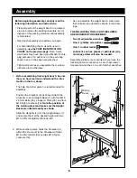
Lubricate the M10 x 178mm Bolt (17). Attach the
Backrest Tubes (5, 42) to the Frame (2) with the
Bolt, two M10 Washers (24), and an M10 Nylon
Locknut (19). 

Secure the Backrest (6) to the Frame (2) with the
Adjustment Pin (32) through one of the three sets
of holes in the adjustment tubes. Secure the
Adjustment Pin with the Pin Clip (27).

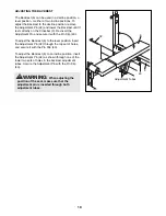
Make sure the Adjustment Pin (32) is com-
pletely inserted through both holes in the
adjustment tubes.

8.

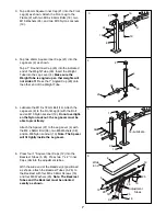
With the wide end of the Seat (11) positioned as
shown, attach the Seat to the brackets on the
Frame (2) with four M6 x 16mm Screws (15).

2

32

5

42

19

27

24

17ÑLubricate

Adjustment

Tubes

6

7

2

11

Wide

End

15

8

9.

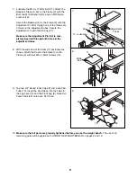
Tap two 3/4Ó Round Inner Caps (9) into each Pad
Tube (10). Insert the Pad Tubes into the holes in
the Leg Lever (4) and the Front Leg (8). Slide two
Foam Pads (22) onto each Pad Tube.

10.

Make sure that all parts are properly tightened before you use the weight bench. 

The use of all

remaining parts will be explained in USING THE WEIGHT BENCH on pages 9 and 10.

10

10

22

4

8

22

9

9

Summary of Contents for Pro 145

Page 1: ...d techni cians on our customer hot line will provide immediate assis tance free of charge to you CUSTOMER HOT LINE 1 800 999 3756 Mon Fri 6 a m 6 p m MST 145 145 CAUTION Read all precautions and instr...

Page 2: ...MENT PARTS Back Cover LIMITED WARRANTY Back Cover Table of Contents The decal shown at the right has been placed on the weight bench If a decal is missing or if it is not legible please call our Custo...

Page 3: ...h does not include weights The weight bench is designed to support a maximum of 460 pounds including the user a weight bar and weights Do not place more that 210 pounds including a weight bar and weig...

Page 4: ...e specific results you want For your benefit read this manual carefully before using the WEIDER PRO 145 weight bench If you have additional questions please call our Customer Service Department toll f...

Page 5: ...ts may have been pre assembled for shipping purposes If you cannot find a part in the parts bags check to see if it has been pre assembled M10 x 81mm Bolt 35 10 M8 x 58mm Bolt 39 1 Spacer 37 1 M6 x 16...

Page 6: ...leared area and remove the packing materials do not dispose of the packing materials until assembly is completed Read each assembly step before you begin For help identifying the small parts used in a...

Page 7: ...the Bolt and an M10 Nylon Locknut 19 Do not overtight en the Nylon Locknut the Leg Lever must be able to pivot freely Attach the Spacer 37 to the Leg Lever 4 with the M8 x 58mm Bolt 39 two M8 Washers...

Page 8: ...n the adjustment tubes 8 With the wide end of the Seat 11 positioned as shown attach the Seat to the brackets on the Frame 2 with four M6 x 16mm Screws 15 2 32 5 42 19 27 24 17 Lubricate Adjustment Tu...

Page 9: ...be cleaned with a damp cloth and a mild non abrasive detergent Do not use solvents Using the Weight Bench ATTACHING WEIGHTS TO THE LEG LEVER To use the Leg Lever 4 slide the desired weights not includ...

Page 10: ...the Pin Clip 43 To adjust the Backrest 6 to the level position insert the Adjustment Pin 32 through the top set of holes and secure it with the Pin Clip 43 To adjust the Backrest 6 to an incline posit...

Page 11: ...reshape and strengthen your body plus develop a stronger heart and lungs PERSONALIZING YOUR EXERCISE PROGRAM We have not specified an exact length of time for each workout or a specific number of rep...

Page 12: ...ule and record your workouts List the date exercises performed weight and numbers of sets and repetitions completed Record your weight and key body measurements at the end of every month Remember the...

Page 13: ...GHT SETS REPS EXERCISE WEIGHT SETS REPS EXERCISE WEIGHT SETS REPS AEROBIC EXERCISE AEROBIC EXERCISE TUESDAY Date WEDNESDAY Date THURSDAY Date FRIDAY Date Make photocopies of this page for scheduling a...

Page 14: ...Inner Cap Key No Qty Description 22 4 Foam Pad 23 1 1 Round Inner Cap 24 4 M10 Washer 25 4 M6 Washer 26 1 Left Backrest Tube 27 1 Pin Clip 28 2 Carriage Bushing 29 1 1 Angled Cap 30 2 M10 x 67mm Adjus...

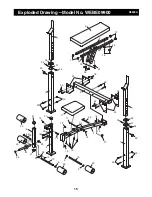
Page 15: ...22 21 21 4 22 23 10 9 9 22 30 31 28 29 10 9 9 22 6 12 12 5 25 16 16 25 25 36 34 34 34 34 39 38 37 38 13 32 2 19 19 15 17 19 19 19 24 8 21 19 14 18 24 24 19 35 20 35 3 20 35 19 33 26 27 Exploded Drawi...

Page 16: ...ty does not extend to any product or damage to a product caused by or attribut able to freight damage abuse misuse improper or abnormal usage or repairs not provided by an ICON authorized service cent...

Reviews: