21
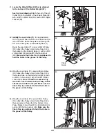
53. Wrap the Press Cable (72) around a 90mm
Pulley (35) in the direction shown. Attach the
Pulley and a Cable Trap (38) to the indicated hole
on the right side of the Press Upright (5) with an
M10 x 121mm Bolt (102) and an M10 Nylon
Locknut (90). Note: Thread the Locknut only
two turns onto the Bolt; another Pulley will be
attached to the Bolt in step 57. Make sure the
Cable Trap is positioned to hold the Cable in
the groove of the Pulley.
53
38
35
5
102
72
90
54. Route the Press Cable (72) through the Press
Frame (17) and around a 90mm Pulley (35) as
shown. Attach the Pulley and a Cable Trap (38) to
the indicated hole on the right side of the Leg
Press Lever (14) with an M10 x 121mm Bolt (102)
and an M10 Nylon Locknut (90). Note: Thread
the Locknut only two turns onto the Bolt;
another Pulley will be attached to the Bolt in
step 56. Make sure the Cable Trap is posi-
tioned to hold the Cable in the groove of the
Pulley.
55. Wrap the Press Cable (72) around a “V”-pulley
(34) in the direction shown. Attach the “V”-pulley
and a Long Cable Trap (37) underneath the Press
Seat Frame (12) with an M10 x 100mm Bolt (115),
an M10 Washer (97), and an M10 Nylon Locknut
(90). Note: the Press Seat Frame has five
adjustment holes. The Pulley must attached at
the second hole from the Leg Press Lever
(14). Make sure the Cable Trap is positioned to
hold the Cable in the groove of the Pulley.
56. Remove the M10 Nylon Locknut (90) used in
step 54.
Wrap the Press Cable (72) around a 90mm
Pulley (35) as shown. Slide a Cable Trap (38)
and the Pulley onto the M10 x 121mm Bolt (102)
in the Leg Press Lever (14). Properly tighten the
M10 Nylon Locknut (90) onto the Bolt. Make sure
the Cable Trap is positioned to hold the Cable
in the groove of the Pulley.
54
55
56
97
72
37
38
35
90 72
115
102
34
90
14
12
14
102
72
38
90
17
14
35


