14108242 Installation, operation and maintenance manual – Squirrel cage motor – WGM20 Line l 35
7.5.1.2
Cooling heads disassembly
After removing the motor end shields, loosen all cables
fastened by clamps on the cooling heads.
Protect the motor internal parts before removing the
cooling heads to avoid wetting them, as there may be
water accumulated inside of the cooling heads channels.
1.
Pull all accessories connecting cables;
2.
Disconnect the connecting cables from the stator
connection box and pass them to inside the motor.
3.
Apply compressed air on the cooling circuit to
eliminate any remaining water and prevent the motor
coil heads from being wetted;
4.
Carefully remove the cooling heads so as not to
damage the gaskets.
NOTE
To disassemble the cooling heads, first
remove the motor end shields, to access the
stator and accessories connection cables.
7.5.1.3
Inspection and cleaning of water
channels
The WGM20 motor allows full access to water circulation
channels.
1.
After disassembling the motor covers and the cooling
heads, perform a detailed visual inspection on all water
channels to identify those that need cleaning;
2.
Protect the motor internal parts (stator, rotor, shaft,
etc.)
3.
Scrape the water channels to unclog the water
passage;
4.
Remove debris from the channels;
5.
Also, clean the inner part and the water inlet and outlet
of the cooling heads, if necessary.
7.5.1.4
End shields and cooling heads
assembly
Before assembling the cooling heads, make sure that the
sealing gaskets, used between the cooling heads and the
motor frame, are in good condition of use, otherwise they
must be replaced.
To mount the motor covers and the cooling heads, follow
the procedure for disassembling these parts in the reverse
order.
NOTES
The sealing gaskets should be assembled
using only the grease to position it inside
the channels. Anaerobic glue should not be
used inside the channels.
All screws that securing the cooling heads
must be tightened according to Table 8.1
or Table 8.2 and locked with chemical lock.
7.6
VIBRATION
Any evidence of increase in the unbalance or vibration of
the motor must be investigated immediately.
7.7
MOTOR OUT OF OPERATION
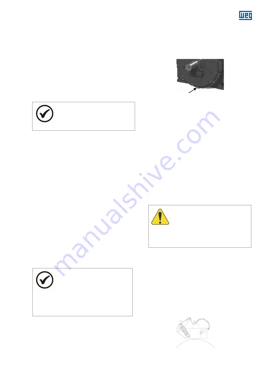
When the motor is stopped, water may condense inside it.
In horizontal motors, this water must be removed through
the drain located at the lowest point of the cooling heads,
as shown in Figure 7.3.
Drain
Figure 7.3: Drain of horizontal motors
In vertical motors, the drain is located in the lower part of
the motor cooling head.
After the motor operation, if it remain stopped for long
term, the water inside the frame must be completely
drained, as follows:
In order to remove the water from the frame of
horizontal motors, disconnect the water supply hoses
and inject compressed air into one of the water inlets
until it drains out completely;
In order to remove the water from the frame of vertical
motors, disconnect the water supply hose and allow it
to drain completely through the lower opening;
For storage during long terms, follow the procedures
described in item 3.3.2 of this manual.
Turn ON the space heaters so that the temperature
inside the motor be kept slightly above the ambient
temperature, avoiding water condensation and
consequent drop of the winding insulation resistance
and oxidation of metallic parts.
ATTENTION
If the motor remains stopped in
environments with negative temperatures,
the freezing of the motor cooling circuit water
must be prevented. This can be done by
draining all the water from the frame or by
using antifreeze additives in the water;
7.8
SHAFT GROUNDING DEVICE
The rear end shield of the WGM20 motor is insulated. This
insulation in the end shield in relation to the rear bearing,
combined with the grounding brush installed in the front
bearing avoids the electric current circulation of the rotor
through the bearings, preventing the bearings from
prematurely failure due to wear caused by electric shocks.
The brush is put in contact with the shaft and connected
by a cable to the motor frame, which must be grounded.
Make sure that the brush holder fastening and its
connection to the frame have been made correctly.
Figure 7.4: Shaft grounding brush
Shaft


