


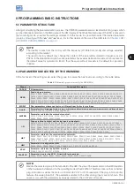


Programming Basic Instructions
5-6 | CFW500
5
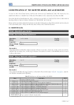
Table 5.3:
Option of parameter P0204
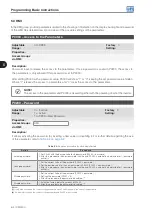
P0204
Action
0 to 4
No Function:
no action.
5
Load WEG 60 Hz:
it loads the default parameters on the inverter with the factory default for 60 Hz.
6
Load WEG 50 Hz:
it loads the default parameters on the inverter with the factory default for 50 Hz.
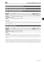
7
Load User 1:
it transfers the content of the memory of parameters 1 to the inverter current parameters.
8
Load User 2:
it transfers the content of the memory of parameters 2 to the inverter current parameters.
9
Saver User 1:
it transfers the current content of the parameters to the memory of parameters 1.
10
Saver User 2:
it transfers the current content of the parameters to the memory of parameters 2.
11
Load Default SoftPLC:
it loads the factory default in SoftPLC parameters (P1010 to P1059).
12 to 15
Reserved.
In order to load the parameters of user 1 and/or user 2 to the CFW500 operating area (P0204 = 7 or 8), it is
necessary that those areas be previously saved.
The operation of loading one of those memories (P0204 = 7 or 8) can also be done via digital inputs (DIx). For
further details referring to this programming, refer to
Section 12.5 DIGITAL INPUTS on page 12-14
NOTE!
When P0204 = 5 or 6, parameters P0296 (Rated voltage), P0297 (Switching frequency) and P0308
(Serial address) are not changed to the factory default.
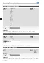
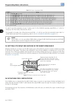
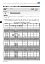
5.5 SETTING OF DISPLAY INDICATIONS IN THE MONITORING MODE
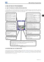
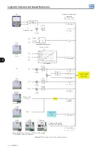
Whenever the inverter is powered up, the HMI display goes to the monitoring mode. In order to simplify the reading
of the inverter parameters, the display was designed to show three parameters simultaneously, at the user’s
discretion. Two of those parameters (main display and secondary display) are shown as numbers and the other
parameter as a bar graph. The selection of those parameters is done via P0205, P0206 and P0207, as indicated
in
.
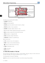
Inverter operating status
Secondary display (selected by P0206)
presents the content of parameter (xxxxx),
number of the parameter (Pxxxx), fault (Fxxx)
or alarm (Axxx) indication
Engineering unit for the main display
(selected by P0209)
Main Display (selected by P0205) presents
the content of parameter (xxxxx), number
of the parameter (Pxxxx), fault (Fxxx) or
alarm (Axxx) indication
Menu
Parameter group selection
Bar graph for parameter monitoring
(selected by P0207)
Figure 5.1:
Screen on initialization and display fields
5.6 SITUATIONS FOR CONFIG STATUS
The CONFIG status is indicated by the HMI “CONF” status, as well as in parameters P0006 and P0680. Such
status indicates that the CFW500 cannot enable the output PWM pulses because the inverter configuration is
incorrect or incomplete.
The table below shows the situations of CONFIG status, where the user can identify the origin condition through
parameter P0047.
Summary of Contents for CFW500 V1.8X
Page 2: ......
Page 4: ......
Page 8: ...Contents...
Page 34: ...General Information 2 4 CFW500...
Page 38: ...About the CFW500 3 4 CFW500 3...
Page 42: ...HMI and Basic Programming 4 4 CFW500 4...
Page 52: ...Programming Basic Instructions 5 10 CFW500 5...
Page 56: ...Identification of the Inverter Model and Accessories 6 4 CFW500 6...
Page 76: ...Available Motor Control Types 8 4 CFW500 8...
Page 84: ...V f Scalar Control 9 8 CFW500 9...
Page 170: ...Communication 17 8 CFW500 17...