


Digital and Analog Inputs and Outputs
CFW500 | 12-5
12
P0233 – AI1 Input Signal
P0238 – AI2 Input Signal
Adjustable
Range:
0 = 0 to 10 V / 20 mA
1 = 4 to 20 mA
2 = 10 V / 20 mA to 0
3 = 20 to 4 mA
Factory
Setting:
0
P0243 – AI3 Input Signal
Adjustable
Range:
0 = 0 to 10 V / 20 mA
1 = 4 to 20 mA
2 = 10 V / 20 mA to 0
3 = 20 to 4 mA
4 = -10 to +10 V
Factory
Setting:
0
Properties:
Access Groups
via HMI:
I/O
Description:
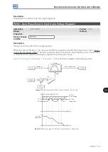
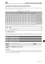
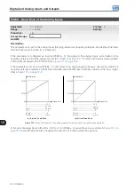
These parameters configure the signal type (if current or voltage) that will be read in each analog input, as well
as its variation range. Note that only AI3 has option 4 (-10 V to +10 V). In options 2 and 3 of the parameters, the
reference is inverted, that is, we have the maximum speed with the minimum signal in the AIx.
In the CFW500 plug-in module, DIP Switch S1:1 in ON configures input AI1 for signal in current. In the other
cases, refer to the installation, configuration and operation guide of the plug-in used.
below summarizes the configuration and equation of the analog inputs.
Table 12.2:
Alx configuration and equation
Signal
P0233,
P0238
P0243
DIP
Switch
Equation AIx(%)
0 to 10 V
0
0
OFF
AIx =
x (100 %) + OFFSET x GAIN
AIx(V)
10 V
(
(
0 to 20 mA
0
0
ON
AIx =
x (100 %) + OFFSET x GAIN
AIx(mA)
20 mA
(
(
4 to 20 mA
1
1
ON
AIx =
x (100 %) + OFFSET x GAIN
(AIx(mA) – 4 mA)
16 mA
(
(
(
(
1
0
10 to 0 V
2
2
OFF
AIx = 100 % –
x (100 %) + OFFSET x GAIN
AIx(V)
10 V
(
(
20 to 0 mA
2
2
ON
AIx = 100 % –
x (100 %) + OFFSET x GAIN
AIx(mA)
20 mA
(
(
20 to 4 mA
3
3
ON
AIx = 100 % –
x (100 %) + OFFSET x GAIN
(AIx(mA) – 4 mA)
16 mA
(
(
(
(
1
0
-10 to +10 V
-
4
OFF
AIx =
x (100 %) + OFFSET x GAIN
AIx(V)
10 V
(
(
For example: AIx = 5 V, OFFSET = -70.0 %, Gain = 1.000, with signal of 0 to 10 V, that is, AIx
ini
= 0 and AIx
FE
= 10.
AIx(%) =
x (100 %) + (70 %) x 1 = -20.0 %
5
10
(
(
Another example: AIx = 12 mA, OFFSET = -80.0 %, Gain = 1.000, with signal of 4 to 20 mA, that is, AIx
ini
= 4
and AIx
FE
= 16.
Summary of Contents for CFW500 V1.8X
Page 2: ......
Page 4: ......
Page 8: ...Contents...
Page 34: ...General Information 2 4 CFW500...
Page 38: ...About the CFW500 3 4 CFW500 3...
Page 42: ...HMI and Basic Programming 4 4 CFW500 4...
Page 52: ...Programming Basic Instructions 5 10 CFW500 5...
Page 56: ...Identification of the Inverter Model and Accessories 6 4 CFW500 6...
Page 76: ...Available Motor Control Types 8 4 CFW500 8...
Page 84: ...V f Scalar Control 9 8 CFW500 9...
Page 170: ...Communication 17 8 CFW500 17...