background image

22

SERVICE AND ADJUSTMENTS

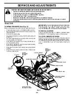
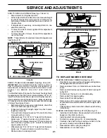
TO REPLACE MOWER BLADE DRIVE BELT
(See Fig. 23)

Park the tractor on level surface.  Engage parking brake.

Remove mower drive belt (See “TO REPLACE MOWER
DRIVE BELT” in this section of this manual).

Remove mower (See “TO REMOVE MOWER” in this
section of this manual).

Remove screws from R.H. mandrel cover and remove
cover.

Carefully roll belt off R.H. mandrel pulley.

Remove belt from center mandrel pulley, idler pulley,
and L.H. mandrel pulley.

Remove any dirt or grass which may have accumulated
around mandrels and entire upper deck surface.

Check secondary idler arm and idler to see that they
rotate freely.

Install new belt in lower groove of L.H. mandrel pulley,
idler pulley, and center mandrel pulley as shown.

Roll belt over R.H. mandrel pulley.  Make sure belt is in
all grooves properly.

Reinstall R.H. mandrel cover.

Reinstall mower to tractor (See “INSTALL MOWER AND
DRIVE BELT” in the Assembly section of this manual).

Reassemble mower drive belt (See “TO REPLACE
MOWER DRIVE BELT” in this section of this manual).

FIG. 23

L.H. MANDREL

SWAY BAR
BRACKET

SECONDARY
IDLER ARM

IDLER PULLEY

MOWER
BLADE
DRIVE BELT

SCREW

R.H.
MANDREL
COVER

CENTER
MANDREL

SPRING

FIG. 24

IDLER
PULLEYS

L.H.
MANDREL
COVER

SCREWS

SMALL
RETAINER
SPRING

CLUTCH SPRING

BELT
KEEPERS

MOWER
DRIVE
BELT

L.H.
MANDREL

FIG. 22

ENGINE
PULLEY

TO REPLACE MOTION DRIVE BELT
(See Fig. 25)

Park the tractor on level surface.  Engage parking brake.  For
assistance, there is a belt installation guide decal on bottom
side of left footrest.

Remove mower (See “TO REMOVE MOWER” in this
section of this manual.)

Remove belt from stationary idler and clutching idler.

Pull belt slack toward rear of tractor.  Carefully remove
belt upwards from transmission input pulley and over
cooling fan blades.

Pull belt toward front of tractor and remove downward
from around engine pulley.

Install new belt by reversing above procedure.

TO ADJUST BRAKE (See Fig. 24)

Your tractor is equipped with an adjustable brake system
which is mounted on the side of the transaxle.
If tractor requires more than six (6) feet stopping distance at
high speed  in highest gear on a level dry concrete or paved
surface, then brake must be adjusted.

Depress clutch/brake pedal and engage parking brake.

Measure distance between brake operating arm and nut
“A” on brake rod.

If distance is other than 1-1/2", loosen jam nut and turn
nut “A” until distance becomes 1-1/2".  Retighten jam nut
against nut “A”.

Road test tractor for proper stopping distance as stated
above.  Readjust if necessary.  If stopping distance is
still greater than six (6) feet in highest gear, further
maintenance is necessary.  Contact your nearest  au-
thorized service center/department.

1-1/2"

WITH PARKING

BRAKE  “ENGAGED”

JAM NUT

DO NOT TOUCH THIS
NUT.  IF FURTHER
BRAKE ADJUSTMENT IS
NECESSARY CONTACT
YOUR NEAREST
AUTHORIZED SERVICE
CENTER/DEPARTMENT

OPERATING
ARM

NUT  “A”

FIG. 25

ENGINE
PULLEY

CLUTCHING
IDLER

STATIONARY
IDLER

TRANSMISSION
INPUT PULLEY

Summary of Contents for 178387

Page 1: ...ANUAL MODEL NO SGT18H46C 18 0 HP 46 Inch LawnTractor For Parts and Service contact our authorized distributor call 1 800 849 1297 For Technical Assistance call 1 800 829 5886 178387 4 6 01 TR PRINTED...

Page 2: ...en changes in speed or direction SAFE OPERATION PRACTICES FOR RIDE ON MOWERS IMPORTANT THIS CUTTING MACHINE IS CAPABLE OF AMPUTATING HANDS AND FEET AND THROWING OBJECTS FAILURE TO OBSERVE THE FOLLOWIN...

Page 3: ...hill disengage blades shift into reverse and back down slowly Do not turn on slopes unless necessary and then turn slowly and gradually downhill if possible Look for this symbol to point out im portan...

Page 4: ...mble and maintain your tractor properly Always observe the SAFETY RULES CUSTOMER RESPONSIBILITIES Read and observe the safety rules Followaregularscheduleinmaintaining caringforand using your tractor...

Page 5: ...prings double loop 4 Retainer Springs single loop 2 Front Link Assemblies 2 Shoulder Bolts 2 Gauge Wheels 2 Washers 3 8 x 7 8 x 14 Gauge 2 Centerlock Nuts Mower Gauge Wheels 1 Oil Drain Tube For Futur...

Page 6: ...ecessary to insure proper tightness FIG 1 HOW TO SET UP YOUR TRACTOR CHECK BATTERY See Fig 2 Lift hood to raised position If this battery is put into service after month and year indicated on label la...

Page 7: ...motion control lever in neutral position Turn ignition key to OFF position Continue with the instructions that follow SEAT PAN SHOULDER BOLT ADJUSTMENT KNOB FLAT WASHER SEAT FIG 3 NOTE You may now ro...

Page 8: ...efrontofmowertoalign deck pins with the holes in suspension arms Retain with double loop retainer springs with loops down as shown Connect anti sway bar to chassis bracket under left footrest and reta...

Page 9: ...h fresh clean regular unleaded gasoline 3 Become familiar with all controls their location and function Operate them before you start the engine 3 Be sure brake system is in safe operating condition 3...

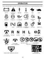
Page 10: ...RD FAST SLOW ENGINE ON ENGINE OFF OIL PRESSURE LIGHTS ON FUEL CHOKE MOWER HEIGHT PARKING BRAKE LOCKED UNLOCKED REVERSE NEUTRAL HIGH LOW ATTACHMENT CLUTCH ENGAGED MOWER LIFT DANGER KEEP HANDS AND FEET...

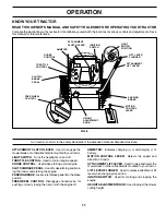
Page 11: ...and starting the engine PARKINGBRAKE Locksclutch brakepedalintothebrake position FREEWHEEL CONTROL Disengages transmission for pushing or slowly towing the tractor with the engine off AMMETER Indicat...

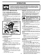
Page 12: ...ause engine to backfire Turn ignition key to OFF position and remove key Always remove key when leaving tractor to prevent unauthorizeduse Never use choke to stop engine PARKING BRAKE ENGAGED POSITION...

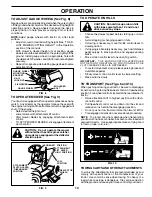
Page 13: ...nditions NOTE Adjust gauge wheels with tractor on a flat level surface Adjust mower to desired cutting height See TO AD JUST MOWER CUTTING HEIGHT in the Operation section of this manual With mower in...

Page 14: ...ake slowly return to operating position Allow one minute for transmission to warm up This can be done during the engine warm up period The attachments can be used during the engine warm up period afte...

Page 15: ...tral N position slowly disengageclutch brakepedal Slowly move motion control lever forward after the tractor moves approximately five 5 feet slowly move motioncontrollevertoreverseposition Afterthetra...

Page 16: ...ery 7 Tighten front axle pivot bolt to 35 ft lbs maximum Do not overtighten 1 12 3 2 5 5 6 7 GENERAL RECOMMENDATIONS The warranty on this tractor does not cover items that have beensubjectedtooperator...

Page 17: ...ear then brake must be adjusted See TOADJUSTBRAKE intheServiceandAdjustments section of this manual TIRES Maintainproperairpressureinalltires See PRODUCT SPECIFICATIONS section of this manual Keep tir...

Page 18: ...fluid mainte nanceisnotrequiredforthelifeofthetransaxle Shouldthe transaxleeverleakorrequireservicing contactyournearest authorizedservicecenter department TO CHANGE ENGINE OIL See Figs 14 and 15 Dete...

Page 19: ...ngtowardscarburetor Be sure there are no fuel line leaks and clamps are properlypositioned Immediately wipe up any spilled gasoline CLAMP FUEL FILTER CLAMP FIG 16 CLEANING Clean engine battery seat fi...

Page 20: ...CLUTCH SPRING INTO SQUARE HOLE IN FRAME TO INSTALL MOWER Follow procedure described in INSTALL MOWER AND DRIVE BELT in the Assembly section of this manual SUSPENSION ARMS RETAINER SPRINGS BOTH SIDES A...

Page 21: ...R TO GROUND GROUND LINE TRUNNION SIDE TO SIDE ADJUSTMENT See Figs 18 and 19 Raise mower to its highest position At the midpoint of both sides of mower measure height from bottom edge of mower to groun...

Page 22: ...arkthetractoronlevelsurface Engageparkingbrake For assistance thereisabeltinstallationguidedecalonbottom side of left footrest Remove mower See TO REMOVE MOWER in this section of this manual Remove be...

Page 23: ...deck height to the lowest position After above adjustment is made if the tractor still creeps forward or backward while motion control lever is in neutral position follow these steps Loosen the adjus...

Page 24: ...CONTROL The choke control has been preset at the factory and adjustment should not be necessary Check adjustment as described below before loosening cable If adjustment is necessary see engine manual...

Page 25: ...G IN ESSENTIAL FUEL SYSTEM PARTS SUCH AS CARBURETOR FUEL FILTER FUEL HOSE OR TANK DURING STORAGE ALSO EXPERIENCE INDICATES THAT ALCOHOL BLENDED FUELS CALLED GASOHOL OR USING ETHANOL OR METHANOL CAN AT...

Page 26: ...tion switch 7 Check replace ignition switch 8 Faulty solenoid or starter 8 Check replace solenoid or starter 9 Faulty operator presence switch es 9 Contact an authorized service center department Engi...

Page 27: ...se blade 6 Replace sharpen blade Tighten blade bolt 7 Buildup of grass leaves and trash under mower 7 Clean underside of mower housing 8 Mower drive belt worn 8 Replace mower drive belt 9 Blades impro...

Page 28: ...28 SERVICE NOTES...

Page 29: ...R TRACTOR IS EQUIPPED WITH A SPECIAL ALTERNATOR SYSTEM THE LIGHTS ARE NOT CONNECTED TO THE BATTERY BUT HAVE THEIR OWN ELECTRICAL SOURCE BECAUSE OF THIS THE BRIGHTNESS OF THE LIGHTS WILL CHANGE WITH EN...

Page 30: ...30 28 29 26 24 42 43 27 27 25 41 27 27 40 33 30 12 12 11 10 8 2 1 27 55 16 22 21 REPAIR PARTS TRACTOR MODEL NUMBER SGT18H46C ELECTRICAL 16 D C AMPE RES 45...

Page 31: ...Cable Battery 6 Gauge 16 Red 25 146148 Cable Battery 26 175158 Fuse 20 Amp 27 73510400 Nut Hex Keps 1 4 20 UNC 28 145491 Cable Ground 6 Gauge 12 Black 29 121305X Switch Plunger 30 175566 Switch Ignit...

Page 32: ...C CHASSIS 59 3 2 35 3 35 3 26 33 10 26 34 1 11 9 66 8 36 87 36 36 29 119 115 71 90 125 28 50 86 120 121 122 17 123 124 19 6 209 3 153 209 209 209 64 209 209 114 117 209 13 209 209 114 117 108 74 30 26...

Page 33: ...50 137304 RodSupportHood 59 110436X Bushing Snap Split 64 170259 DashLower 66 169261X010 Plate Dash Slkscr 71 73640400 Nut Keps Hex 1 4 20 Unc 74 73680600 Nut Crownlock 3 8 16 Unc 86 136670X550 Panel...

Page 34: ...110 110 59 51 42 31 38 61 41 42 40 73 103 102 94 3 142 53 35 55 36 42 62 35 36 131 140 22 39 34 89 69 16 1 96 111 51 56 64 65 19 72 63 116 70 57 93 141 26 25 19 24 2 26 26 95 27 26 127 37 139 19 77 7...

Page 35: ...9132012 Washer 13 32 x 1 1 4 x 12 Ga 73 158282 StrapTorqueRhHydro 3000 76 12000053 E Ring 77 9396E Key Square 1 4 x 2 81 165598 Shaft Asm Cross Tapered 82 123782X Spring Torsion 83 19171216 Washer 17...

Page 36: ...OR MODEL NUMBER SGT18H46C STEERING ASSEMBLY 38 38 12 39 1 41 42 37 36 37 5 9 5 7 7 9 4 3 32 43 6 43 8 10 40 11 8 6 9 46 46 8 6 9 2 47 47 92 15 15 15 29 29 29 29 82 85 85 68 67 67 67 13 65 26 30 28 88...

Page 37: ...8 X 16ga 29 17060612 Screw3 8 16x3 4 30 76020412 Pin 32 130465 Rod Tie Wire Form 19 75 Mech 36 145207 Bushing Strg 37 152927 Screw TT 10 32 x 5 x 3 8 Flange 38 140045X428 Insert Cap Strg 39 100712K Wa...

Page 38: ...38 REPAIR PARTS TRACTOR MODEL NUMBER SGT18H46C ENGINE 32 31 34 33 37 33 41 40 39 2 1 OPTIONAL EQUIPMENT Spark Arrester 29 26 25 4 23 45 8 10 62 6 5 72 13 99 45 100 45 14 38 105 16 105 3 81 107 106...

Page 39: ...ng Debris Guard 25 132778 ChokeControl 26 73920600 Nut Keps 3 8 24 UNF 29 137180 Kit Spark Arrestor 31 151346 Tank Fuel 3 50 Rear 32 161493 CapFuelGauge 33 123487X Clamp Hose 34 106082X Pad Spacer 37...

Page 40: ...Bolt Carriage 1 4 20 x 1 1 2 15 121249X Spacer Split 11 1 24 16 15 12 13 17 25 28 7 28 7 27 18 2 6 22 21 5 10 5 14 KEY PART NO NO DESCRIPTION 16 123740X Spring 17 123976X Locknut Flange 1 4 Grade 5 1...

Page 41: ...r Side 19 162391 Decal Deck 142341 Decal Cntrl Movement 157199X428 Pad Footrest 138311 Decal Handle Lft Height Adjust 178387 Manual Owner s English WHEELS TIRES 14 6 2 1 5 8 4 10 3 9 11 7 NOTE All com...

Page 42: ...42 REPAIR PARTS TRACTOR MODEL NUMBER SGT18H46C MOWER LIFT 36 15 20 16 1718 20 20 15 20 46 47 23 24 25 27 28 29 37 41 40 38 12 11 31 32 31 32 19 19 13 13 13 13 42 43 39 44 30 49 26 50 6 1 14 2 7 8 9 10...

Page 43: ...Special 24 19131016 Washer 13 32 x 5 8 x 16 Ga 25 137150 SpringCompression 26 76020308 Pin Cotter 27 160985 Rod Adj Lift 28 73350600 Nut Hex Jam 3 8 16 Unc 29 138057 Knob Inf 3 8 16 Unc 30 150233 Tru...

Page 44: ...44 33 30 30 32 21 21 22 23 24 25 26 20 27 28 29 18 18 21 34 132 31 44 35 130 62 72 52 38 1 134 133 82 39 32 31 129 60 62 61 59 136 135 126 41 42 58 46 45 18 8 9 10 11 13 16 48 14 15 47 69 127 85 19 5...

Page 45: ...Hardened 45 145059 Cover Mandrel Deck 46 137729 Screw Thdroll 1 4 20 x 5 8 47 144959 V Belt Mower Secondary 48 139573 V Belt Mower Primary 49 73680600 Nut Crownlock 3 8 16 UNC 50 72110612 Bolt Carriag...

Page 46: ...limited to 90 days from the date of original purchase 5 This Warranty applies only to products which have been properly assembled adjusted operated and main tained in accordance with the instructions...

Page 47: ...IGHTING GUIDE ONLY RIDE UP AND DOWN HILL NOT ACROSS HILL SUGGESTED GUIDE FOR SIGHTING SLOPES FOR SAFE OPERATION Operate your Tractor up and down the face of slopes not greater than 15 never across the...

Page 48: ......
Reviews: