


WELD THE WORLD
Cod. 006.0001.1420
08/09/2021 V.2.12
Multi Power 204T
11
ENGLISH
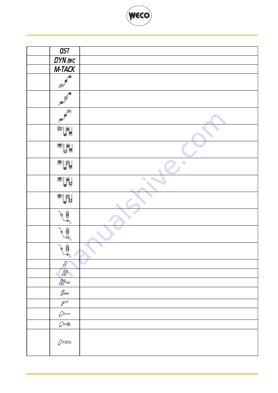
L13
Illumination shows that the following parameter can be set: Q-START
L14
Illumination shows that the following parameter can be set: DYNAMIC ARC
L15
Illumination shows that the following parameter can be displayed: MULTI TACK
L16
Illumination shows that the following parameter can be set: STARTING CURRENT (%/A)
L17
Illumination shows that the following parameter can be set: SLOPE UP (s)
L18
Illumination shows that the following parameter can be set: WELDING CURRENT (A)
L19
Illumination shows that the following parameter can be set: SECOND CURRENT B-LEVEL (%)
L20
Illumination shows that the following parameter can be set: BASE CURRENT (A)
L21
Illumination shows that the following parameter can be set: PEAK TIME (s)
L22
illumination shows that the following parameter can be set: BASE TIME(s)
L21 + L22
illumination shows that the following parameter can be set: PULSED CURRENT FREQUENCY
(Hz/kHz)
L23
illumination shows that the following parameter can be set: SLOPE DOWN (s)
L24
illumination shows that the following parameter can be set: STARTING CURRENT (%/A)
L25
illumination shows that the following parameter can be set: POST-GAS (s)
L26
Illumination shows that the following function has been activated: 2 stroke procedure.
L27
Illumination shows that the following function has been activated: 4 stroke procedure.
L28
Illumination shows that the following function has been activated: 4 stroke Bi-level procedure
L29
Illumination shows that the following function has been activated: 2 stroke spot procedure
(SPOT).
L30
This LED illuminates to show that the following welding mode is selected: MMA
L31
This LED illuminates to show that the following welding mode is selected: TIG DC CONTINU
-
OUS
L32
This LED illuminates to show that the following welding mode is selected: PULSED DC TIG
L33
This LED illuminates to show that the following welding mode is selected: SYNERGIC PULSED
TIG
When this is on, it means that the synergic mode is active and that the operator can set just the
welding current while the other parameters are automatically regulated by the machine. The
synergy is optimised by angle welding.


