


2 -
Security
Page 3
Intended use
Page 3
General safety instructions
Page 3
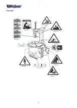
Hazard signs
Page 4
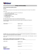
Setup and Assembly
Page 5
Initial commissioning by a qualified technician
Page 5
EC Declaration of Conformity
Page 6
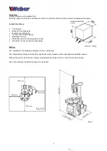
Unpacking
Page 7
Drafting
Page 7
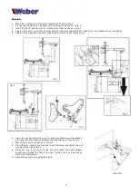
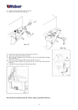
Structure
Page 8
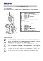
Usage and maintenance
Page 11
Description of the machine
Page 11
Warning and hazard symbols
Page 11
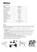
Technical Specifications
Page 12
Maintenance
Page 12
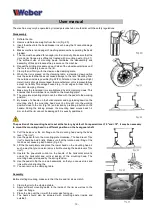
User manual
Page 13
Disassembly
Page 13
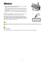
Assembly
Page 14
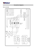
Connection diagrams
Page 15
Diagram electric cabling
Page 15
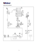
Pressure air supply schedule
Page 16
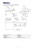
Schematic pressure air supply Chip table and Booster
Page 17
The information in this manual has been carefully checked, but errors cannot be completely excluded. This manual is
intended for users with technical knowledge of vehicle inspection and repair. We reserve the right to make technical and
content changes.
Last update of the manual: February 2018.
Table of contents
Summary of Contents for 1228 Monster
Page 4: ...4 Hazard signs...
Page 15: ...15 Connection diagrams Electric circuit diagram...


