background image

18 

CR 9-II CCD 2.0

Maintenance overview

Maintenance interval

Maintenance point Maintenance activity

After the first 

25 operating hours

Engine

– Change the engine oil

–  Check valve play; 


adjust if necessary

–  Re-tighten all accessible 

threaded connections

Every 8 operating 

hours / daily

Air filter

–  Clean air filter insert, 

check for damage, 

replace if necessary

Every 150 operating 

hours / every  6  months

Engine

Battery

Gearshift

– Change the engine oil

– Change the fuel filter

– Change the oil filter

–  Check acid level, top up 

with distilled water if 

necessary

– Check the oil level

Every 150 operating 

hours / every  year

Gearshift

Exciter

– Change oil

– Change oil

Every 250 operating 

hours

Engine

–  Check valve play; 


adjust if necessary

The regulations of the engine manufacturer must be complied with in addition to the above main-

tenance overview!
Tasks must be executed using proper tools, and the safety instructions of this operating and 

maintenance manual must be complied with for all tasks.

All maintenance work: select collection vessels large enough to prevent oil from spilling onto the 

ground. Dispose of waste oil in an environmentally friendly manner (regulation on waste oils).

Dispose of oils, greases, cloths soaked in oil, and replaced parts with oil on them in an environ-

mentally friendly manner.

If lubricating oils and fuel come into contact with skin, they can cause skin cancer. Upon contact 

with the skin, clean affected skin with suitable cleaning agent without delay.

If accessible during maintenance, check the condition and stability of all screws.

Summary of Contents for CR 9-II

Page 1: ...erating and Maintenance Manual 0619 englisch bersetzung der Orioginal Betriebsanleitung Weber Maschinentechnik GmbH Im Boden 5 8 10 D 57334 Bad Laasphe R ckershausen Germany Tel 49 0 27 54 398 0 Fax 4...

Page 2: ...2 CR 9 II CCD 2 0...

Page 3: ...raphic presentation 8 Device description 10 Technical data 11 Activities prior to starting work 13 Starting 14 Compacting 15 Shutting down 17 Maintenance overview 18 Maintenance work 19 Operating flui...

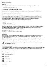
Page 4: ...ncrease the reliability and service life of your soil compactor This operating and maintenance manual must always be available at the implementation site of the soil compactor If necessary you can obt...

Page 5: ...he owner shall be exclusively responsible All liability is rejected if damage occurs due to non compliance with this provision This risk is borne solely by the user Easily foreseeable misuse Any use f...

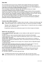
Page 6: ...areas or in areas that are poorly ventilated tunnels caves covered pits etc Be particularly cautious when operating the engine in the vicinity of people and livestock Maintenance and repair work Only...

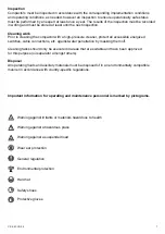
Page 7: ...itches cable connections etc against water penetration by masking them off Cleaning tasks should only be executed in areas that are suitable and have been approved for this purpose oil separator among...

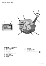
Page 8: ...phic presentation Overall view CR 9 II CCD 2 0 1 Engine no image 9 Gas lever 2 Drive lever 10 Attachment plates 3 Guide bar 11 COMPATROL 4 Lifting ring 12 Hearing protection sticker 5 MDM motor protec...

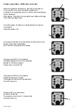
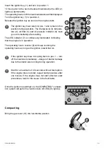
Page 9: ...peration Operating status OK Oil pressure indicator 4 is illuminated Oil pressure too low Engine shuts down immediately Error must be corrected prior to restart Graphic presentation MDM motor protecti...

Page 10: ...the engine speed between idle and full throttle The guide bar is used to steer the soil compactor Forward and reverse is variably controlled via the drive lever attached to the guide bar Function of t...

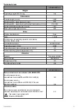
Page 11: ...stroke diesel Operating speed 1 min 2900 Operating speed ground dependent in m min 28 Incline capacity ground dependent in 35 Vibration System Two wave vibrator Drive concept Mechanical Frequency in...

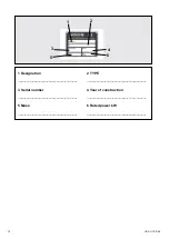
Page 12: ...12 CR 9 II CCD 2 0 2 1 3 4 5 6 1 Designation 2 TYPE 3 Serial number 4 Year of construction 5 Mass 6 Rated power kW...

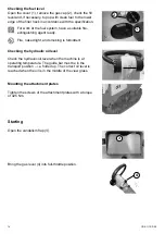
Page 13: ...apacity of 1000 kg Do not step under suspended loads Adjusting the guide bar Adjust the desired work height of the guide bar with the set screw 4 Checking the engine oil level Open the maintenance cov...

Page 14: ...he attachment plates Tighten the screws of the attachment plates with a torque of 425 Nm Checking the fuel level Open the cover 1 remove the gas cap 2 check the fill level and if necessary top up with...

Page 15: ...permanently Theoperatinghoursuntilthenextmaintenancewillbedisplayed Turn the ignition key 1 to position 2 Release the ignition key as soon as the engine starts The ignition key must return to pos 1 an...

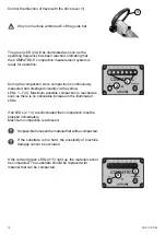
Page 16: ...uously measured and displayed visually via the yellow LEDs 1 7 3 Maximum possible compaction is reached as soon as there is no noticeable increase in the illuminated LEDs If all LEDs 2 3 are illuminat...

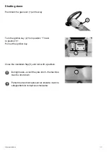
Page 17: ...he ignition key 2 from position 1 back to position 0 Pull out the ignition key Close the vandalism flap 3 and lock with a padlock During breaks even if they are short the machine must be shut down Par...

Page 18: ...ngine Check valve play adjust if necessary The regulations of the engine manufacturer must be complied with in addition to the above main tenance overview Tasks must be executed using proper tools and...

Page 19: ...tick 3 Only drain engine oil when at operating temperature When working in the area of the engine compartment there is danger of being burned Screw the oil drain pipe 5 onto the engine drain valve 4 a...

Page 20: ...nt there is danger of being burned Risk of scalding due to hot oil Selectcollectionvesselslargeenoughtopreventoilfrom spilling onto the ground Dispose of waste oil in an envi ronmentally friendly mann...

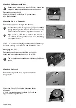
Page 21: ...manner regulation on waste oils Wipe up off oil slick and oil residue and dispose of fuel soaked cleaning cloths in an environmentally responsible manner To fill tilt the machine slightly and fill wit...

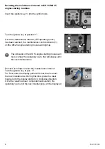
Page 22: ...module will light up The indicator on the MS 15 engine starting module will merely show the operating hours that will elapse until the next maintenance Proceed as follows to reset the maintenance inte...

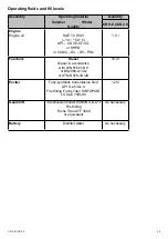
Page 23: ...SHPD or CCMC D4 D5 PD2 1 9 l Fuel tank Diesel Diesel in accordance with DIN 51601 DK or BS2869 A1 A2 or STM D975 1D 2D 10 0 l Exciter Fully synthetic transmission fluid API GL 5 GL 4 First filling Fuc...

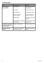
Page 24: ...fuse defective Execute start process as prescribed Check the fuel level Change the fuel filter See Hatz operating manual section 4 1 4 Clean change air filter cartridge Remove charge battery replace...

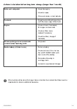
Page 25: ...evel mark Check air filter clean replace if necessary Check fuel filter change if necessary All bare parts gas lever accelerator control cables fastening bolts Oil grease Starter battery if there is o...

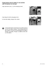
Page 26: ...e charging socket Insert plug 2 into the charging socket Connect the battery charger to the mains Complywiththedevicemanufacturer soperatingmanual for use of the battery charger The operating manual o...

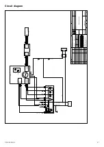
Page 27: ...G 15 30 75 83 50 Index nderung Datum Name Gepr Bearb Name Datum Ma stab Masse Ident Nr Masch Typ Druckdatum Benennung Schutzvermerk nach DIN ISO 16016 beachten Dokumentenart CAD EAGLE Blatt Orig Webe...

Page 28: ...28 CR 9 II CCD 2 0...

Page 29: ...CR 9 II CCD 2 0 29...

Page 30: ...30 CR 9 II CCD 2 0...

Page 31: ...e SARL 14 rue d Arsonval 69680 Chassieu Telephone Fax E mail 33 0 472 791020 33 0 472 791021 france webermt com in Poland WEBER Maschinentechnik Sp zo o Ul Jeziorki 86 02 863 Warszawa Telephone Fax E...

Page 32: ...Vibration plates Vibrating tampers Vibration rollers Joint cutters Internal vibrators and converters Weber MASCHINENTECHNIK GmbH Im Boden 57334 Bad Laasphe R ckershausen Telephone 49 0 27 54 398 0 Fax...

Reviews:

Related manuals for CR 9-II