


11
Do not terminate condensate drain line within three 3’ (914mm) of any outlet of engine,
generator exhaust systems, compartment housing an engine or generator, nor in a bilge, unless
the drain is connected properly to a sealed condensate or shower sump pump. Seal all
condensate hose penetrations.
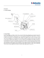
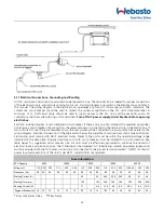
4.6 Blower Assembly
You can achieve multi-directional supply air discharge from a single unit by rotating the blower to the desired position.
It is ideal for tight installations as 180° of rotation is available with which to position the blower. Its advanced design
allows the blower to be easily removed for rotating or servicing by removing 4 screws. Rotate the blower to allow the
most direct flow of air to the supply air grille.
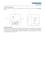
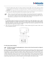
4.7 Mounting Brackets
The A/C unit is supplied with a base pan that also serves as a
condensate pan. Mounting clip brackets (4) are provided to
secure the base pan to a flat, horizontal surface.
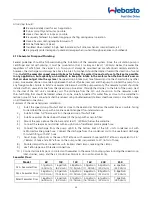
4.8 Supply & Return Air Grilles and Transition Boxes
Install the supply air grille as high as possible in a location that
will provide uniform air distribution throughout the cabin. Grille
louvers should be directed upward. The return air grille should
be installed as low and close to the A/C as possible to insure
direct uninterrupted airflow to the evaporator. The return air
grille should have a minimum four inches (4') of clearance in
front of it, free from any furniture or other obstructions. In no
instance should a supply air discharge be directed towards a
return air grille, as this will cause the system to short cycle.
Allow for adequate clearance behind the supply air grille(s) for
the transition box and ducting connection. See the
Maintenance section of this manual for return air filter cleaning
instructions.
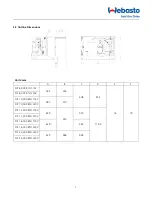
Model
6K
10K
12K
16K
20K
25K
Min. Return Air
Grilles Size (re.)
75in²
(48500mm²)
100in²
(65680mm²)
105in²
(76514mm²)
160in²
(103584mm²)
240in²
(153028mm²)
240in²
(153028mm²)
4.9 Ducting
Good airflow is critical for the performance of the entire system. The static pressure should not exceed 100 Pa. It is
highly dependent on the quality of the ducting installation. The ducting should be run as straight, smooth and taut as
possible minimizing the number of 90 degree bends (two tight 90° bends can reduce airflow by 25%). If a transition
box is used, the total area of supply air ducts going out of the box should at least equal the area of the supply duct
feeding the box. To calculate the square inch area of a round duct, multiply the radius by itself (r2) and multiply that
number by 3.1416(
π
). The following is a summary of proper ducting connections:
1
)
Pull back the fiberglass insulation exposing the inner Mylar duct hose.
2
)
Slide the Mylar duct hose around the mount ring until it bottoms out.
3
)
Screw 3 or 4 stainless steel sheet metal screws through the duct hose into the transition ring. Make sure to
catch the wire in the duct hose with the heads of the screws. Use finish washers with the screws if necessary.
Do not use band clamps, as the hose will slide off.
4
)
Wrap duct tape around the ducting and ring joint to prevent any air leaks.
5
)
Pull the insulation back up over the Mylar to the ring and tape this joint.
6
)
Remove excess ducting and use the same connection method at the supply air grille.
Summary of Contents for FCF 10
Page 2: ......
Page 16: ...16 4 13 2 20K 25K Units mm ...
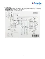
Page 19: ...19 WIRING DIAGRAM 12K 115V 12K 230V The specification of power cord is AWG12 3 3 2 5 ...
Page 20: ...20 WIRING DIAGRAM 16K 115V 16K 230V The specification of power cord is AWG12 3 3 2 5 ...
Page 30: ...30 NOTES ...
Page 31: ...31 NOTES ...