


2
Installation
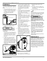
This pump is designed to be self-priming
when installed and operated as specified
below.
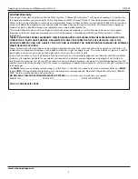
1. The pump should be placed as close as
possible to the water being pumped.
A pump with 20 foot suction lift will
not remove water as quickly as a
pump with 5 foot suction lift
(Figure 1).
2. Suction hose and fitting must be
airtight.
An
air
leak
in
the suction line may prevent priming
of the pump. Use of thread sealant is
recommended.
Suction lines must be reinforced hose
or rigid pipe. Non-reinforced hose will
collapse due to the suction created
by the pump and prevent pump from
operating.
3. A check valve must be used in the
suction line to maintain the self-
priming capability. If no check valve is
used the pump will need to be primed
at the start of each operation. For best
operation, the check valve should be
installed at the intake of the suction
line.(Figure 2).
4. A suction strainer is required to filter
abrasive material. Abrasive material,
such as gravel, will destroy the pump
and void the warranty. This pump
is not designed to handle abrasive
materials.
5. The discharge hose and fitting should
be leak-tight. A leak in the discharge
hose will allow water to spray
around the work site, making the site
hazardous.
6. Keep all pipes and hose lines as short
and straight as possible. Long lengths
and curves in the pipes and hose lines
will reduce the pressure the pump
develops.
7. Fill the engine crankcase with oil.
Refer to the engine operating manual
for the specific grade of oil and
amount required.
8. Fill the engine fuel tank with
gasoline. Refer to the engine
operating manual for specific gasoline
type that is most efficient for this
engine.
9. Add water to the priming port on
the pump (See Figure 3). Continue
adding water until the water level is
approximately 3 inches from the top.
Install the priming plug. The water in
the pump will create the suction that
primes the pump.
10. Turn fuel valve to ‘ON’ position
11. Move choke level to ‘CHOKE’ position.
12. Move the engine switch to ‘ON’
position.
13. Pull engine crank until engine starts.
Once engine starts, move choke lever
to ‘RUN’ position.
14. The pump will take several minutes to
prime.
PIPING
Always place the pump as close as possible
to the water being pumped. Keep all pipe
and hose lines as short and straight as
possible.
Support
pump
and piping when assembling and after
installation. Failure to do so may cause
piping to break, pump to fail, etc; all of
which can result in property damage and/or
personal injury.
All suction connections must be airtight.
If the pump won’t prime, check for leaks
in the suction piping or fittings. If flexible
suction hose is used instead of pipe, use
reinforced hose with a two inch inner
diameter. Non-reinforced flexible hose may
collapse from the vacuum created as the
pump primes.
Always use a strainer at the end of the
suction pipe or hose. Position strainer so
it doesn’t become clogged with stones
or debris. A suction line check valve is
recommended.
Do not use this pump for suction lifts over
twenty-five feet.
Maintenance
Always shut off the engine, allow the
engine to cool, and remove the spark plug
before performing any maintenance.
During freezing weather, open the drain
port and allow all the water in the pump
to drain. This will prevent damage to the
pump when the water freezes. If the pump
will be stored for a month or more, drain
the water from the pump and follow the
engine manufacturer’s recommendations
for long-term storage.
Operating Instructions and Replacement Parts List
Figure 1
20 Ft. Suction Lift
5 Ft.
Suction
Lift
Figure 2
Check valve
Figure 3
Priming port
Suction
Drain port
Discharge
www.waynepumps.com


