


DOOR INSTALLATION
INSTRUCTIONS
Before installing your door, be certain that you have read and followed all of the instruc-
tions covered in the pre-installation section of this manual. Failure to do so may result in an
improperly installed door.
NOTE:
Reference TDS 160 for general garage door terminology at
www.dasma.com
.
IMPORTANT:
IF THE DOOR WILL BE EXPOSED TO A SIGNIFICANT AMOUNT OF ROAD SALT,
PAINT THE BARE GALVANIZED BOTTOM WEATHER STEEL RETAINER TO INHIBIT RUSTING.
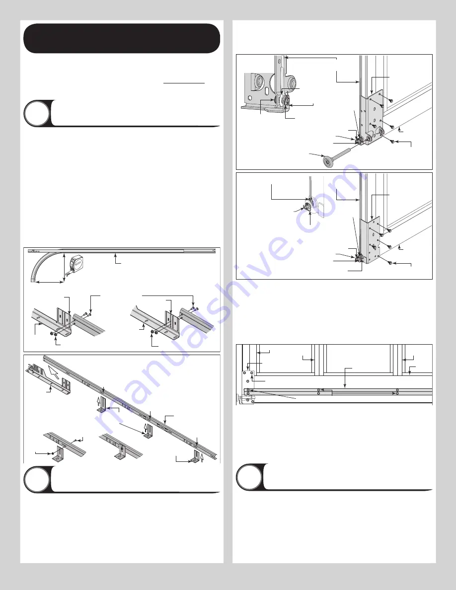
Attaching Flag Angles and Jamb Brackets To
Vertical Tracks
1
NOTE:
If you have Riveted Track or Angle Mount Track, skip this step.
FOR DOORS WITH FULLY ADJUSTABLE TRACK:
Hand tighten the left hand flag angle to
the left hand vertical track using (2) 1/4” - 20 x 9/16” track bolts and (2) 1/4” - 20 flange
hex nuts.
NOTE:
The bottom jamb bracket is always the shortest bracket, while the center jamb
bracket is the next tallest. If three jamb brackets per side are included with your door, you will
have received a top jamb bracket, which is the tallest.
To attach the bottom jamb bracket, locate lower hole of the hole/ slot pattern of the 1st hole
set on the vertical track. Align the slot in the jamb bracket with the lower hole of the hole/ slot
pattern. Hand tighten jamb bracket using (1) 1/4” - 20 x 9/16” track bolt and (1) 1/4” – 20
flange hex nut.
Place the center jamb bracket over the lower hole of the hole/ slot pattern that is centered
between the bottom jamb bracket and flag angle of the 2nd hole set. Hand tighten jamb
bracket using (1) 1/4” - 20 x 9/16” track bolt and (1) 1/4” - 20 flange hex nut.
If a top jamb bracket was included, hand tighten it to vertical track using the lower hole of the
hole/ slot pattern in the 3rd hole set and (1) 1/4” - 20 x 9/16” track bolt and (1) 1/4” - 20
flange hex nut.
(2) 1/4”- 20 x 9/16”
Track bolts
(2) 1/4”- 20
Flange hex nuts
12” Radius track
15” Radius track
(2) 1/4”- 20 Flange hex nuts
Slot
Slot
Left hand
flag angle
Left hand
flag angle
12” Or 15”
Radius
Horizontal
track
Left hand
vertical track
NOTE:
Loosely fasten components
together. Repeat the same process for the
right hand side.
Left hand
flag angle
Left hand
jamb bracket
Left hand
jamb bracket
3rd
Set
1st
Set
2nd
Set
1/4”- 20 x 9/16”
Track bolt
1/4”- 20
Flange hex
nut
Attaching Bottom Corner Brackets
2
NOTE:
Refer to door section identification, located in the pre-installation section of this
manual. Refer to Package Contents / Breakdown of Parts, to determine which bottom corner
brackets you have received.
Uncoil the counterbalance lift cables and locate the left hand bottom corner bracket. Starting
on the left hand side, place the cable loop into position between the two holes on the side of
the left hand bottom bracket. Slide a clevis pin through the innermost hole, cable loop, and
outermost hole, of the bottom corner bracket. Secure the clevis pin in place by inserting a
cotter pin into the hole of the clevis pin. Bend the ends of the cotter pin outwards to secure it
in place. Repeat for other side.
IF YOU DID NOT RECEIVE AN ANTI-SAG BRACE:
Next, align the bottom corner bracket
horizontally with the bottom edge of the bottom section and also align the bottom corner
bracket vertically with the left bottom edge of the bottom section. Attach each bottom corner
brackets to the bottom section using the appropriate 1/4” - 20 x 7/8” self drilling screws, as
shown.
Bottom section
Counterbalance
cable loop
Short stem track roller
Left hand bottom
corner bracket
Counterbalance
lift cable
Clevis pin
Bottom
weather seal
Washer
(5) 1/4”-20 x 7/8”
Self drilling screws
Cotter pin
Counterbalance
cable loop
Cotter pin
Washer
Clevis pin
Left hand
bottom corner
bracket
Bottom section
Counterbalance
cable loop
Left hand bottom
corner bracket
Counterbalance
lift cable
Clevis pin
Bottom
weather seal
Washer
(5) 1/4”-20 x 7/8”
Self drilling screws
Cotter pin
Counterbalance cable loop
Cotter pin (attached into
place from opposite side
of bottom corner bracket)
Clevis pin (inserted through cotter pin
and bent into place)
Counterbalance
cable loop
IF YOU DID RECEIVE AN ANTI-SAG BRACE:
Next, align the bottom corner bracket hori-
zontally with the bottom edge of the bottom section and also align the bottom corner bracket
vertically with the left bottom edge of the bottom section. With the bottom corner brackets in
position on the bottom section, locate and center the anti-sag brace onto the bottom section
surface and against the roller carriers of the bottom corner brackets. Secure the anti-sag
brace and the bottom corner brackets to the bottom section using (2) 1/4” - 20 x 7/8” self
drilling screws at each end stile. Next, secure the anti-sag brace to the bottom section using
(2) 1/4” - 20 x 7/8” self drilling screws at each center stile location(s). Finish securing the
bottom corner bracket to the bottom section using 1/4” - 20 x 7/8” self drilling screws, as
shown above.
Typical bottom section shown
End stile
Center
stile
Center
stile
Bottom
rail
Anti-sag brace
(1.8” x 1.8” x 11ga.
angles welded together)
(if provided)
1/4” - 20 x 7/8” Self drilling screws
Typical bottom
corner bracket
1/4” - 20 x 7/8”
Self drilling screws
NOTE:
If you have broken cable safety devices, only install the top (4) 1/4” - 20 x 7/8” self
drilling screws to secure the bottom corner bracket to the bottom section. Reference Step
Broken Cable Safety Devices.
NOTE:
If you did not receive Track Roller Carriers or Cable Keepers, then insert a short stem
track roller with roller spacer into each of the bottom corner brackets, as shown.
NOTE:
Verify that the bottom weather seal (bottom seal) is aligned with door section. If there
is more than 1/2” excess bottom weather seal on either side, trim bottom weather seal even
with door section.
Attaching Track Roller Carrier’s
3
NOTE:
If you don’t have track roller carriers, then skip this step. Refer to Package Contents /
Breakdown of Parts, to determine if you have track roller carriers.
Starting on left hand side of the bottom section, attach the track roller carrier with the stamp
“STD” facing UP to the bottom corner bracket by aligning the four holes of the track roller
carrier with the four holes in the bottom corner bracket. Secure the track roller carrier to the
bottom corner bracket with (4) 1/4” - 20 x 7/8” self drilling screws.
NOTE:
If you did not receive cable keepers, then insert a short stem track roller with roller
spacer into each of the bottom corner brackets, as shown.
IMPORTANT:
THE TRACK ROLLER CARRIER’S INNER HOLES ARE USED ON DOORS WITH 2”
8