
3
Configuring the DIP switches
The Click 110 should be configured using the DIP switches, The DIP switches on the circuit board can be used to change
input mapping and the baud rates used for bus 1 and bus 2. These parameters can also be changed using the two other
configuration options.
Note.
Using the DIP switches to configure puts the Click 110 into hardware mode. In hardware mode the settings can be
viewed, but not changed via Click Supervisor and the front panel menu.
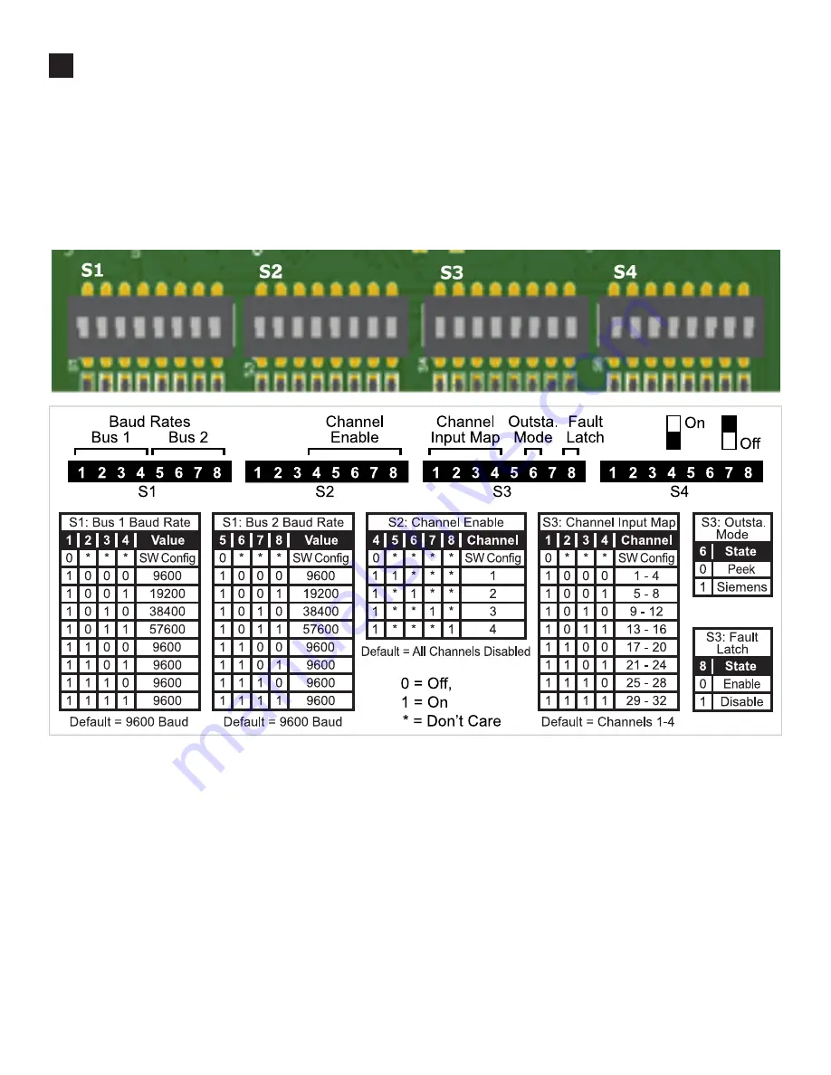
Look at the figure below to see how to set the switches in order to configure the parameters. To turn a switch on, flip it up.
Baud rate for Bus 1 and Bus 2
This function lets you set the baud rate for bus 1 and bus 2. The two buses can be configured separately. Flip the switches up
and down according to the diagram to set the baud rate for each bus. All cards should be set to 9600 baud.
Channel output mapping
Any combination of outputs can be enabled. A disabled output will never enter the detection state and will never indicate a fault
condition. Due to limited space on the faceplate side label, not all combinations of enabled and disabled channels are listed.
Channel input mapping
This function lets you map four of the input data channels coming from the sensor to the output channels on the device. The
outputs are assigned sequentially, so if you select 13-16, then input 13 will be mapped to channel 1 and input 14 will be mapped to
channel 2. The table below shows an example of a 10 and 6 lane setup.
Note.
The lanes need to be renamed from the default name of “Lane_01” to “#01” using the SSMHD software. Please check the
outstation information card to confirm lane assignments as there can be some variation.


