3: Installation
APCD-LM047-2.1
21
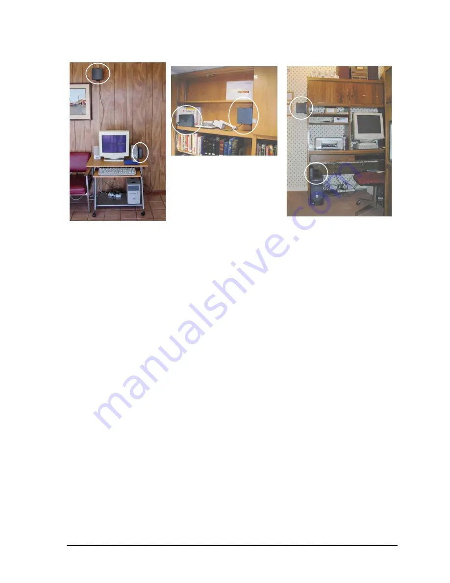
Figure 7 Typical Installations of EUM3005
3.3.2 Mounting and Orienting the EUM3005 Antenna
Once a good location for the antenna has been selected, mount the antenna as required, Use
the drywall plugs and screws if you are attaching the antenna to the wall. Note that the
antenna holding bar has a release tab at one end. It is recommended that this tab be the upper
tab when mounting the holding bar vertically.
When the EUM3005 antenna holding bar has been positioned and attached, the best
orientation of the modem should be determined by trying different angles and seeing which
give the highest signal strength and signal quality.
3.3.3 Connecting the End-User’s PC
There are many ways to connect the EUM3005 to the end-user’s PC, using Ethernet switches,
IP routers, etc. The discussion below is for the simplest, most direct method of connection.
1. Connect the end-user’s PC by attaching a crossover Ethernet cable between the
Ethernet port on the end-user’s computer and the Ethernet port on the modem.
2. Plug the power supply into the EUM3005 first, then into the AC socket. Wait 10
seconds for the EUM3005 to come up.
3. Check the Ethernet LEDs on the Ethernet interface of the modem and/or end-user’s
PC to ensure the Ethernet connection between the EUM3005 and the end-user’s PC
is active. Refer to
Table 1 on page 8
for an explanation of the Ethernet LEDs normally
provided on Ethernet interface cards.
4. When attempting to send data to, or receive data from, the Internet, check the
Ethernet Traffic LED to ensure data transmission is taking place. This LED flashes as
data traffic passes between the end-user’s PC and the EUM3005.


