Read and understand this manual
prior to installing, operating or servicing this equipment.
Operation and Maintenance Manual
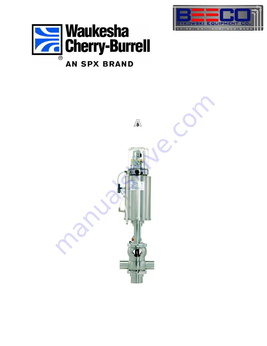
W75RS PMO Double Seat Mix Proof Valves
with the W-Series 2-Piece Control Module
Page 1: ...Read and understand this manual prior to installing operating or servicing this equipment Operation and Maintenance Manual W75RS PMO Double Seat Mix Proof Valves with the W Series 2 Piece Control Module ...
Page 2: ...ange without notice and does not represent a commitment on the part of SPX Corporation No part of this manual may be reproduced or transmitted in any form or by any means electronic or mechanical including photocopying and recording for any purpose without the express writ ten permission of SPX Corporation Copyright 2008 SPX Corporation All Rights Reserved Revision Date August 2008 Publication 95 ...
Page 3: ...at Options 7 Pressure Ratings 7 Installation 8 Location 8 Welding Instructions 8 Air Supply 8 Flow Direction 8 Fittings 8 Pipeline Support 9 Stem Flush Adapter 9 Installing the Valve 9 Connecting Flush Supply Line Optional 10 Operation 11 Solenoid Valve Port Connections 11 Automatic Fail Safe System 12 Valve Operating Conditions 13 Valve Open 13 Valve Closed 13 Valve Closed Upper Seat Lifted 13 Va...
Page 4: ...nt 19 Radial Seal Installation 20 Lower Bearing Carrier O ring and Bearing Replacement 20 Actuator O ring and Bearing Replacement 21 Control Top Removal and Disassembly 22 Removal from Valve 22 Switches 22 Micro Switch 22 Proximity Switch 22 Switch Adjustment 23 Parts Lists 24 W75RS PMO Double Seat Mix Proof Valves Seat Lift 24 W75RS PMO Double Seat Mix Proof Valves Seat Lift with Flush 26 W75RS P...
Page 5: ...lied including without limitation any warranty of merchantability of fitness for a particular purpose The foregoing sets forth Seller s entire and exclusive liability and Buyer s exclusive and sole remedy for any claim of damages in connection with the sale of products In no event shall Seller be liable for any special consequential incidental or indirect damages including without limitation attor...
Page 6: ...its and equipment before working on or near exposed circuit parts Locking and Interlocking Devices These devices should be checked for proper working condition and capability of performing their intended functions Make replacements only with the original manufacturer s renewal parts or kits Adjust or repair in accordance with the manufacturer s instructions Periodic Inspection Industrial equipment...
Page 7: ...leach do not exceed concentrations of 150 ppm available chlorine do not exceed contact time of 20 minutes and do not exceed temperatures of 104 F 40 C Corrosion discoloration deposits or pitting may occur under product deposits or under gaskets Keep surfaces clean including those under gaskets or in grooves or tight corners Clean immediately after use Do not allow equipment to set idle exposed to ...
Page 8: ...e of signaling whether the upper and or lower seat is in the proper location W75RS PMO valves are air operated air to raise Factory Inspection Each Waukesha Cherry Burrell valve is shipped completely assembled lubricated and ready for use Models and Specifications Materials Product Wetted ASTM 316L UNS S31603 DIN 1 4404 Non Product ASTM 304 UNS S30400 DIN 1 4301 Seat Material Tri Ring optional Ela...
Page 9: ... cases install the solenoid valves in a separate solenoid cabinet Seal Material Fluorelastomer FKM EPDM Thermal Range of Application 32 F to 375 F 0 C to 190 C 0 F to 275 F 18 C to 135 C Chemical Resistance Contact WCB Application Engineering for other fluid compatibility Silicone oil and grease Hot water and steam up to 275 F 135 C Aliphatic chlorinated and aromatic hydrocarbons Many organic and ...
Page 10: ...e performed before installation CAUTION Before attempting to buttweld an automatic valve into a line disassemble the body from the actuator Dissipate heat away from the valve body to prevent warping Prior to installation remove the stem actuator assembly and lower bearing carrier Remove all seals from the body Weld the body into position ensuring that the connection is free of tension and distorti...
Page 11: ...m The valves are designed for 14 5 psi 1 bar maximum flush pressure with 1 4 6 35 mm tube OD connections WARNING Milk and milk products are to be flushed from the piping system and isolated prior to installation of valve or optional flush line Installing the Valve 1 Connect the air lines to Port A Switch the controls to open condition pressurize connection 3 See Figure 3 2 Using caution lift the a...
Page 12: ...opening and CIP cleaning fluid escapes from the drain port Drain off to prevent possible hazard to personnel Regulate the flush supply for pressures of 30 psi minimum 50 psi maximum Maximum solution temperature is 180 F 60 C WARNING The cavity cleaning operation must fall within the fail safe control system See Cleaning on page 15 For PMO applications consult the PMO for suitable water requirement...
Page 13: ...en the spring only acts on the upper seat stem to hold the upper and lower plugs together When the valve is closed the spring holds the lower plug in closed position Solenoid Valve Port Connections Typically three air supplies controlled by solenoid valves supply air to the valve actuator Figure 5 The air supply must be 72 to 100 psi 4 9 to 6 9 bar ON Solenoid energized OPEN OFF Solenoid de energi...
Page 14: ...input signal when upper seat is properly closed The valve seats are part of an automatic fail safe system preventing contamination of product with cleaning or sanitizing solutions Automatic fail safe systems are unique to each particular installation Typically both blocking valve seats are properly seated in blocked position before the mechanical cleaning system can be activated for the cleaning c...
Page 15: ... Chambers 3 1 and 2 are vented Large spring closes the valve to fail safe position See Figure 8 Figure 7 Valve Open Figure 8 Valve Closed Valve Closed Upper Seat Lifted For cleaning the upper seat on seat lifting models only Chamber 2 is pressurized and Chambers 3 and 1 are vented See Figure 9 Valve Closed Lower Seat Push For cleaning the lower seat Chamber 3 is pressurized and Chambers 1 and 2 ar...
Page 16: ... lock out the pumps 1 With the valve fully closed confirm that the proximity switches conform to Table 2 on page 12 Verify the switch status on the PLC control system 2 Pressurize chamber 1 to open the valve Confirm that the proximity switches conform to Table 2 on page 12 3 Vent chamber 1 to close the valve 4 Activate the upper seat lift either through the control system or manually by supplying ...
Page 17: ... and assembly procedures Use food grade non petroleum silicone grease on seals and o rings Apply Bostik Never Seez White Food Grade with PTFE or equivalent to all bolts and threaded stem parts Cleaning CAUTION Avoid splashing any liquid into the air vent of the actuator during clean up Cleaning In Place CIP CIP methods can be used to clean installed automatic valves without disassem bly Methods mu...
Page 18: ...hree seconds per cleaning cycle Cleaning Procedure Cleaning procedures should be established for each installation depending on product characteristics operating parameters temperature velocity valve cycles product velocities etc WARNING Do not clean the vent until milk and dairy products have been removed or isolated from the valve For optional external flush of the vent cavity water flush can be...
Page 19: ...he adjusting nut Figure 13 item A Left to increase right to decrease Removing Valve from System WARNING Before removing the actuator valve stem assembly from the valve body drain all product lines connected to the body 1 Clean rinse and drain the pipe system elements attached to the valve Remove or block the fluid and gas lines to prevent material from entering the pipe system elements attached to...
Page 20: ...actuator and slide the adapter off the outer stem 2 Remove and replace the o ring Figure 17 item A inside the adapter 3 Check the split bearing Figure 17 item B inside the adapter by feeling the amount protruding from the adapter wall If the bearing is flat against the wall replace the bearing 4 Place a screw driver behind the bearing and pry it away from the wall of the adapter A needle nose plie...
Page 21: ...3 Lubricate the new Tri Ring Figure 18 item A with an acceptable cleansing solution or lubricant 4 Place the stem through a 1 1 8 inch 30 mm hole bored through a board secured by a vise 5 Start the Tri Ring as shown in Figure 18 6 Using the installation tool part number 102797 Figure 18 item B press the Tri Ring into the plug at locations A B C and D Figure 19 If the tool is not used DO NOT use a ...
Page 22: ...rier wall If the bearing is flat against the wall replace the bearing 3 Place a screw driver behind the bearing and pry it away from the wall of the lower bearing carrier A needle nose pliers can be used to grip the bearing for removal 4 To install a new bearing coil the bearing to a size smaller than the inside diameter of the adapter and insert it into the proper location 5 Push the actuator ste...
Page 23: ...y are worn or damaged 6 Inspect the bearings item C If the bearing does not extend slightly above the edge of the metal surface replace the bearing 7 The bearing is split to allow it to be removed from the groove Place a screw driver behind the bearing and pry it away from the wall of the yoke A nee dle nose pliers can be used to grip the bearing for removal NOTE The bearing will be damaged during...
Page 24: ...ed electrician should disconnect the power Disassembly 1 Remove the valve from service 2 Shut off the delivery of air 3 Disconnect the electrical supply and lock out the power CAUTION Only an authorized electrician should disconnect the power 4 Unscrew the single piece clear top and remove it 5 To remove solenoids unscrew them from the base taking care with the wires 6 To disassemble the proximity...
Page 25: ...et the distance between the switches and the stem shaft at 0 040 1 mm If using a micro switch place a 0 020 feeler gauge between the roller and the small diameter of the stem Adjust the switch toward the stem until a click is heard 2 Hand tighten the cap screws Figure 24 item A to hold the switch position 3 With the stem raised adjust the vertical height of the upper switch target to slightly belo...
Page 26: ...Parts Lists Waukesha Cherry Burrell Page 24 95 03076 August 2008 Parts Lists W75RS PMO Double Seat Mix Proof Valves Seat Lift ...
Page 27: ...9 E80343 E80354 FKM V90328 V90333 V90339 V90343 V90354 14 W iping Seal Lower EPDM 116192 116197 116201 116203 116773 FKM 116193 116198 116202 115624 116774 15 Bearing 106049 106048 102003 112560 114232 16 Lower Stem Assembly 116530 116546 116560 116276 116577 17 Seal Retainer 116529 116544 116559 116272 114226 18 Clamp 119 34 119 51 119 87 119 71 113827 20 Adapter Upper 116523 116538 116553 Lower ...
Page 28: ...Parts Lists Waukesha Cherry Burrell Page 26 95 03076 August 2008 W75RS PMO Double Seat Mix Proof Valves Seat Lift with Flush ...
Page 29: ...V90328 V90333 V90339 V90343 V90354 14 W iping Seal Lower EPDM 116192 116197 116201 115624 116773 FKM 116193 116198 116202 116203 116774 15 Bearing 106049 106048 102003 112560 114232 16 Lower Stem Assembly 119725 116721 119666 119623 119654 17 Seal Retainer 116529 116544 116559 116272 114226 18 Clamp 119 34 119 51 119 87 119 71 113827 19 Spray Bushing 115388 115388 115388 115388 115388 20 Adapter U...
Page 30: ...Parts Lists Waukesha Cherry Burrell Page 28 95 03076 August 2008 W75RS PMO Double Seat Mix Proof Valve Actuator ...
Page 31: ...T00400 3 4 122039 11 O ring Nitrile N70219 12 Yoke 1 1 2 116818 Valve Size 6 Diameter 2 116776 Visual Indicator Stem 1 1 2 ACT00391 2 1 2 116834 2 ACT00392 3 116938 2 1 2 ACT00393 4 114209 3 ACT00394 Yoke flush 1 1 2 119871 4 ACT00395 2 119873 Control Top Indicator Stem 1 1 2 ACT00401 2 1 2 119875 2 ACT00402 3 119877 2 1 2 ACT00403 4 119879 3 ACT00404 14 Bearing Main Piston 102052 4 ACT00405 15 Be...
Page 32: ...tion 1 1 2 2 2 1 2 3 4 1 Buttweld A1 117683 117678 117672 115380 117574 2 Buttweld B1 117685 117680 117674 115382 117576 3 Buttweld B2 117687 117682 117676 115384 117577 4 Buttweld B3 117686 117681 117675 115383 117578 5 Buttweld C1 117684 117679 117673 115381 117575 6 Buttweld E1 116533 116548 116563 115379 116580 PL5027 CH142 ...
Page 33: ...ing Leakage through outer stem Inner stem o ring failure Replace o ring Operation Valve fails to open Air pressure too low Set air pressure to 72 psi 5 bar minimum Control failure Check control sequence Check control wiring and power source Valve fails to close Controls failed Check control sequence Check control wiring and power source Upper seat fails to lift during seat lift Lifting piston not ...
Page 34: ...Troubleshooting Waukesha Cherry Burrell Page 32 95 03076 August 2008 Notes ...
Page 35: ......
Page 36: ... please visit www spxpe com SPX Corporation reserves the right to incorporate our latest design and material changes without notice or obligation Design features materials of construction and dimensional data as described in this bulletin are provided for your information only and should not be relied upon unless confirmed in writing Certified drawings are available upon request Issued August 2008...