
3/2010
11579
r1
Please
Recycle
2800 De La Cruz Blvd.
Santa Clara, CA 95050
Phone: 800.879.8585
www.wattstopper.com
PLUG n’ GO OPERATION (PnG)
The plug load circuit connected to the LMPL-101 is automatically controlled
by all occupancy sensors on the DLM local network. After the last occupancy
sensor’s time delay expires or when a switch button bound to the LMPL-100 is
operated, the LMPL-101 shuts off the plug load circuit.
TROUBLESHOOTING
Loads do not operate as expected.
LEDs on a switch or
sensor don’t light
1. Check to see that the the device is connected to the DLM local network.
2. Check for 24VDC input to the device: Plug in a different DLM device at the device location. If
the device does not power up, 24VDC is not present.
• Check the high voltage connections to the plug load controller.
• If high voltage connections are good and high voltage is present, recheck DLM local
network connections between the device and the plug load controller.
The wrong lights and plug
loads are controlled
1. Configure the switch buttons and sensors to control the desired loads using the Push n’
Learn adjustment procedure.
LEDs turn ON and OFF but
load doesn’t switch
1. Make sure device is not in PnL.
2. Check load connections to room controllers and/or plug load controllers.
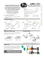
Load ON/OFF button
Blue LED ON when
load is ON
Config button &
red LED
UNIT ADJUSTMENT - PUSH n’ LEARN (PnL)
Load Selection Procedure
Before testing or adjusting the DLM local network load
configuration, plug a lamp or radio into one of the electrical
outlets on the controlled plug load circuit.
A configuration button (Config) allows access to our
patented Push n’ Learn™ technology to change binding
relationships between sensors, switches and loads.
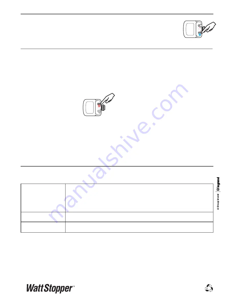
Step 1: Enter Push n’ Learn
Press and hold the Config button
(on any DLM device) for 3 seconds.
The red LED on the LMPL-101
begins to blink faster (2x per
second) as does the red LED on
ALL other communicating devices
connected to the DLM local network.
The red LEDs continue to blink until you exit PnL mode.
All loads in the room turn OFF immediately after
entering PnL, then one load will turn ON. This is Load
#1, which is bound to switch button #1 and occupancy
sensors as part of the Plug n’ Go factory default setting.
All switch buttons and sensors that are bound to this
load have their blue LED solid ON.
Step 2: Load selection
Press and release the Config button to step through the
loads connected to the DLM local network. As each load
turns ON note the devices (switch buttons and sensors)
that are showing a bright solid blue LED. These devices
are currently bound to the load that is ON. The blue LED
on the room controller or plug load controller connected
to the load is also lit.
• To
unbind
a switch button from a load, press the
switch button while its blue LED is ON bright. The
blue LED goes dim to indicate the button no longer
controls the load that is currently ON.
• To
unbind
an occupancy sensor, press the up (
)
or
down (
) adjustment button while its blue LED is
ON. The blue LED turns OFF to indicate the sensor no
longer controls the load that is currently ON.
Pressing the switch or up (
)
or down (
) button again
while the load is ON
rebinds
the load to the button or
sensor and the blue LED illuminates brightly.
Step 3: Exit Push n’ Learn
Press and hold the Config button until the red LED turns
OFF, approximately 3 seconds.


