


5
STEP 2
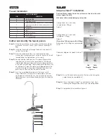
Faucet Installation
Gather and identify the faucet pieces.
Step A -
Place the escutcheon chrome plate and the black rubber
washer on the faucet shank . (Parts found in faucet parts
bag) .
Step B -
Insert the faucet shank through the hole in sink and let it
rest on the sink top .
Step C -
From the underside of the sink, slide on the location
washer, lock washer and brass nut onto the shank . Check
for orientation the tighten brass nut securely .
Step D -
Locate the Blue tube from the UF module . Measure the
tube from the unit over to the faucet and cut it to the de-
sired length . Remove a brass nut, plastic sleeve and brass
insert from the parts bag . To assemble, place the brass nut
on the tube first, then the sleeve (small tapered end of the
sleeve must point to the end of tube) and then insert the
brass insert all the way into the end of the tube .
Step E -
Push the assembled blue tube into the faucet until it
stops . Slide brass nut and plastic sleeve down until you
can thread nut onto the faucet . Use a wrench to securely
tighten the brass nut while continuing to push the tube into
the faucet .
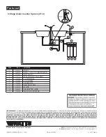
PaRtS LISt FOR FaUCet
IteM
DeSCRIPtION
A
Escutcheon Plate
B
Black Rubber Washer
C
Black Locating Washer (use where a
1
⁄
2
" hole is available,
reverse when mounting on stainless steel or when using
drilled hole)
D
Lock Washer
E
Nut
F
Brass Insert (sleeve)
G
Plastic Sleeve
H
1
⁄
4
" Compression Nut
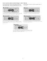
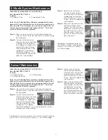
Adapt-A-Valve™ Installation
Caution: Water supply line to the system must be from the cold
water supply line only.
Hot water will severely damage your system.
Configuration for
1
⁄
2
inch valve
(using no brass fittings)
Figure 1
Configuration for
3
⁄
8
inch valve
(using brass fittings)
Figure 2
(Do not use Teflon tape on this fitting.)
Both sides of this fitting are compression
seals .
Placement diagram for Adapt-A-Valve™
Figure 3
Step A –
Turn off the cold water supply to the faucet by turning the
angle stop valve completely off .
Step B –
Attach the Adapt-A-Valve™ as illustrated in Fig 2, Fig 3,
choosing the configuration that fits your plumbing needs
Step C –
Completed Valve installation Figure: 3 .
STEP 3
Figure 1
Figure: 2
Figure: 3
Hot
Supply
Cold
Supply
A
B
C
D
E
F
G
H


