background image

8

EN

ENGLISH

HK-HKM-25-32-IM-DE-W-UK-03-2021-Rev.3 | Part no. 10025988

7  Installation and commissioning

DANGER

Electrical energy!

Risk of death from electric shock.

•  Work on parts carrying live voltage must be carried out by 

qualified electricians only.

•  Disconnect the power supply of the system and secure it to 

prevent it from being switched on again before carrying out 
any installation, maintenance, cleaning or repair work.

NOTICE

The installation and commissioning of

the pump group must be carried out only by trained person-
nel who have been authorized by the manufacturer. 

!

!


CAUTION

When repairing the unit or replacing

parts, be sure to observe the specified installation positions 
and flow directions of the parts being replaced!

!

!


CAUTION

Material damage!

Pressure shocks may occur if the stop valve is opened or 
closed quickly.

•  Always open and close the stop valves slowly and in a 

controlled way.

7.1  Installation diagram

Fig. 7-1: Installation diagram

7.2  Installation

All screw fittings must be checked and tightened if 
required prior to installation and commissioning!

Torque:

•  3/4" fittings 35 Nm
•  1" fittings 55 Nm
•  11/4" fittings 90 Nm
•  11/2" fittings 130 Nm
•  2" fittings 190 Nm

Requirement

•  The valves are pre-installed at the factory but must be 

checked for leaks during commissioning (pressure test).

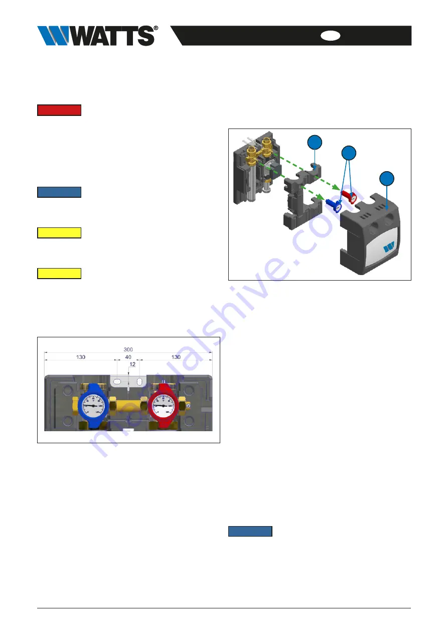
1.  Dismantle the front panel (A) of the pump group.

C

A

B

Fig. 7-2: Dismounting of the front and intermediate insulation

2.  Mark the drilling points for installing pump group (see „Fig. 

7-1: Installation diagram“).

3.  Drill the holes corresponding to the screw and anchor size 

(see „Fig. 7-1: Installation diagram“).

4.  Place the anchor.
5.  Screw the screws into the anchor.
6.  Place the pump group to the wall in a vertical installation 

position (see „Fig. 7-1: Installation diagram“) .

7.  Screw the screws into the anchor.
8.  Remove the thermometer handles (B) and dismount the 

intermediate insulation (C).

9.  Connect the supply and return lines and check that all 

screw connections are tight.

7.3  Initial commissioning

Requirement

•  The pump group is completely assembled.

Connection of the power supply

1.  Connect the power supply (see separate pump 

documentation).


9

The pump group switches on automatically after being 
connected to the power supply.

2.  Vent the heating system.

NOTICE

The pump group must be switched off

during the ventilation process!

3.  Mount intermediate insulation (C) and attach thermome-

ter grips (B).

4.  Mount the front panel of the pump group.

Summary of Contents for HK25 Series

Page 1: ...WattsWater eu Series HK HKM 25 32 Pump groups for unmixed and mixed heating circuits DN 25 and DN 32 Installation and Operating Manual translated from the original operating manual...

Page 2: ...t conformity A Declaration of Conformity according to the Machinery Directive 2006 42 EC has been issued for this pump group product 1 3 Product features stable mounting bracket including mounting har...

Page 3: ...for mounting on a wall The pump group is not intended to be operated by people including children with physical sensory or mental disabilities nor by people with insufficient experience or previous k...

Page 4: ...Axis center distance 125 mm Sealing surfaces distance 342 5 mm Connections to pipe network Heating circuit top HK25 HK25 KH HKM25 11 2 male connection flat sealaing Fitting 11 2 union nut x 1 female c...

Page 5: ...2 Pressure loss mbar 1 10 100 1 000 100 1 000 10 000 100 000 Flow rate l h HK25 HK25 KH HK32 Fig 4 1 Pressure loss curves HK25 HK25 KH and HK32 Pump mixing valve groups HKM25 HKM32 Pressure loss mbar...

Page 6: ...5 12 5 300 40 130 130 A A 125 G1 1 2 G1 1 2 15 342 5 12 5 300 40 HK25 HK32 HKM25 HKM32 A 1 F 11 4 F A 1 F 11 4 F Fig 5 1 Dimensions HK25 and HK32 Fig 5 2 Dimensions HKM25 and HKM32 125 G11 2 130 130 R...

Page 7: ...KH 1 Ball valve with gravity brake 1 supply 2 Ball valve return 3 Circulation pump 4 Wall bracket 5 Distance pipe 6 Additional ball valve only HK25 KH 7 Bypass connection pipe only HKM 8 3 way mixer...

Page 8: ...55 Nm 11 4 fittings 90 Nm 11 2 fittings 130 Nm 2 fittings 190 Nm Requirement The valves are pre installed at the factory but must be checked for leaks during commissioning pressure test 1 Dismantle th...

Page 9: ...er supply and secure it against being switched on again 2 Loosen the nuts on the pump bottom connection 3 Turn the pump and the flow ball valve by 180 degrees 4 Rotate the nut on the return ball valve...

Page 10: ...tools materials and other equipment used from the working area Vent the system 8 2 Replacement of wear parts Please note that the pump group contains parts that for technical reasons are subject to we...

Page 11: ...y mixer HKM 1 Replace damaged or defective seals if necessary 2 Install the 3 way mixer M and tighten the union nuts 3 Mount the motor S 4 Slowly open the ball valves by turning the thermometer handle...

Page 12: ...pump group properly or commission a specialist company to do so 3 Sort the assemblies and component parts into recyclable materials hazardous substances and operating materials 4 Dispose of the assemb...

Reviews: