


3
Before servicing, shut down the water system and lock out the
system, if possible. Then use the following procedure to remove the
check assemblies.
Before servicing, be certain the shutoff valves are closed. Then use
the following procedure to remove the check assemblies.
1. Slowly open all ball valves to relieve air and water pressure.
Loosen the bolts on the groove coupler and remove the groove
coupling and cover plate from the valve body.
2. (For check #1) Using a
9
⁄
16
" socket wrench or nut driver, remove
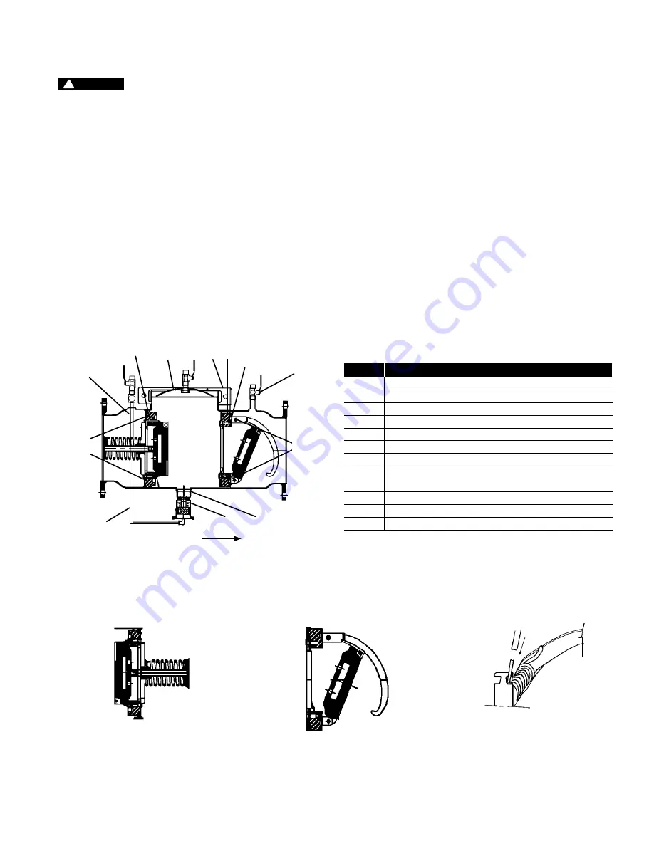
the four nuts from the check #1 studs. (See Figure 1.) Using two
hands, place one at 12 o’clock and the other at 6 o’clock, and
wiggle the check assembly free. Remove the check through the
access port with the back of the clapper first, spring end down.
Pull the check assembly out of the main body. Inspect the seats
and clapper sealing surfaces. (See Figure 2.)
(For check #2) After loosening the bolts with a
9
⁄
16
" socket, re-
move the bolts completely. Using the centerline access bar, spin
the check assembly from the 9 o’clock position to the 12 o’clock
position. Without letting go of the access bar, push the cam
assembly slightly downstream to make the clapper parallel to the
valve body. (See Figure 3.) Bring the check assembly through the
check retaining wall, leaving the check assembly parallel to the
valve body. Pull the check assembly through the access port.
3. To relieve the torsion spring tension, place a
3
⁄
8
" nut driver or a
piece of small diameter pipe on the check arm torsion spring,
and move it around and away from the torsion spring retaining
bracket. (See Figure 4.) This allows the check arm to move freely,
enabling inspection of the clapper face and check seat. Thor-
oughly clean the seat area and clapper sealing surfaces, check
arms, and O-rings for damage, nicks, and debris. If any damage
is observed, install a new check assembly or O-ring, or both.
4. Before reinstalling the check assembly, thoroughly clean the
O-ring groove and lubricate the O-ring with an FDA Approved
lubricant.
1
5
7 2
3
10
9
11
4
6
Check
Studs
Check
Bolts
Flow
Servicing the First and Second Checks
WARNING
!
Depressurize valve before servicing.
ITEM
DESCRIPTION
1
#1 Cam-Check
2
#2 Cam-Check
3
#1 Cam-Check O-ring
4
#2 Cam-Check O-ring
5
Cover Plate
6
Ball Valve
7
Groove Coupler
8
Groove Coupler Gasket (not shown)
9
Relief Valve (complete assembly)
10
Relief Valve Hose
11
Relief Valve Body O-ring
12
Washer, Shutoff
Figure 1
Figure 2
#1 Cam-Check RP
Figure 3
#2 Cam-Check DC & RP
Figure 4