background image

4

Watlow Series 935A User’s Manual

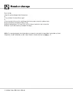
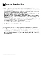
Read or change

You can simply:

• Read the normally displayed actual temperature,

or…

• Press and hold 

ß

to read the set point,

or…

1. Press and hold  

.

and  

,

simultaneously for three seconds to move to a software menu.

2. Press and hold 

ß

to display a choice or value.

3. While continuing to press 

ß

, press 

.

or 

,

to choose new data or select a new value.

4. Release 

ß

and the arrow key to complete the change.

NOTE: The normally displayed actual temperature and set point can be altered to show different combinations of actual
temperature, set point temperature, or time in hours:minutes or minutes:seconds. See 

[dISP] 

p. 16.

Summary of Contents for 935A Series

Page 1: ...nual Registered Company Winona Minnesota USA TOTAL 3Y earWarranty CUSTOMER SATISFACTION Series 935A Temperature Controller with Countdown Timer 1241 Bundy Boulevard P O Box 5580 Winona Minnesota USA 5...

Page 2: ...low controller review all configuration informa tion to verify that your selections are consistent with your application inputs outputs alarms limits etc If the problem persists after checking the abo...

Page 3: ...mity 52 Software Map 55 How to Reach Us back cover Table Numbers Page 1 Output Functions 3 2 Error Messages and Action 8 3 Software Organization 9 4 Operations Menu Overview 11 5 PID Menu Overview 14...

Page 4: ...operator interface and user s manual Compact panel footprint 1 32 DIN size Water and corrosion proof IP65 NEMA 4X rated Reliable built to UL CUL approved safety standards with a three year warranty Ac...

Page 5: ...2 Electromechanical Relay Switched dc or Solid state Relay Table 1 Valid Output Functions First select Output 1 Then select Output 2 Heat None Cool Alarm Timer Cool None Heat Alarm Timer Alarm None He...

Page 6: ...o move to a software menu 2 Press and hold to display a choice or value 3 While continuing to press press or to choose new data or select a new value 4 Release and the arrow key to complete the change...

Page 7: ...p 16 Clears a latched alarm LED 1 Lit when Output 1 is active LED 2 Lit when Output 2 is active RDY Lit when the process temperature is inside the timer ready band Up Increment Down Decrement Arrow Ke...

Page 8: ...ing the thermal system as soon as you apply power to it 2 Look at the Series 935A s display It is reading actual temperature set point temperature or time To change set point go to p 7 The Series 935A...

Page 9: ...tual process temperature when it comes from the factory You can change it to normally display the set point or time Go to p 16 see dISP 1 Press and hold 2 Press one of the arrow keys to alter the set...

Page 10: ...Check the sensor bad connection or replace as broken wire necessary Electrical noise Cycle power to system See if error clears Check system for electrical interference Control is inoperable Check for...

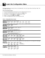
Page 11: ...after Timer Select Set Point Type Go to PID Menu Configuration Menu PID p 12 Set Heat PID Functions Dead Band Cool PID Functions Calibration Offset Configuration p 16 Set Inputs Functions Output Types...

Page 12: ...t Point is active both before and after the timing sequence The normal or Primary Set Point con trols during the timing sequence Local Remote Set Point L r L or r Choose to maintain control with the P...

Page 13: ...etween Alarm Low and Range High or OFF ALO Alarm Low Countdown Timer Select a countdown time duration 0 0 9959 00 00 to 99 59 Hrs Min or Min Sec Idle Set Point Type Choose to track set point or select...

Page 14: ...h the Operations Menu with until you see the Pid prompt 3 While pressing to display no choose YES with or 4 Release to see the first PID prompt NOTE Access to the PID Menu and the prompts there varies...

Page 15: ...off cycle Range Switched dc Solid State Relay 0 1 to 60 0 seconds Default 5 0 seconds Range Electromechanical Relay 5 0 to 60 0 seconds Default 30 0 seconds Dead Band db Dead Band adjusts the effectiv...

Page 16: ...R or Switched dc Electromechanical Relay Dead Band Select a dead band value 0 999 0 555 0 99 0 0 55 0 0 F to 999 F or 0 C to 555 C or 0 0 F to 999 0 F or 0 0 C to 555 0 C Set Up Cool Proportional Band...

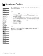
Page 17: ...u and the prompts there varies with lockout function and output set up The PID Menu is locked out when the 935A leaves the factory Lockout function the Lockout Tag tAg function masks menus from view i...

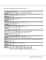
Page 18: ...between Input Type Range Low and Input Range High Input Range High Select highest displayable set point Ranges p 21 Rl In Select a value highest displayable set point between Input Type Range High an...

Page 19: ...Function Choose the start timer conditions IMd Immediate start on a press rdy press and Actual temp is inside the Ready Band rdYA press plus Actual temp is inside the Ready Band then acknowledge with...

Page 20: ...onfiguration Operation Auto tune you can choose to mask those items from view and therefore from change For example In the Configuration Menu tAG set up if you can see the P the opera tor cannot see t...

Page 21: ...Yes No Yes Yes View Change PID No Yes Yes No Yes Yes Yes RDY 2 1 SET fpl PCOA No Lockout Fully Locked Operator s Perspective Set Point Lockout Front Panel Lockout Security Tag Three Lockout Options No...

Page 22: ...tter Front Panel Lock FPL requires an external switch and 62 0 5 watt resistor wired in parallel on Output 1 Switch open unlocked closed locked See p 23 Output 2 sets timer interval in hours minutes t...

Page 23: ...tion Choose Output 1 type hEAt COOL ALM rsP FPL nonE Heat Cool Alarm Remote Front None Set Panel Point Lock Output 2 Function Choose Output 2 type dependent on Output 1 choice hEAt COOL ALM thM tMS no...

Page 24: ...Set Point will display instead of Primary Set Point Auto tune always uses the Primary Set Point Deviation Alarm uses the active Set Point Figure 5 Remote Set Point Wiring See p 42 45 for more wiring i...

Page 25: ...anel Lock switch will cause the panel to lock out even when the switch is open Injury to personnel or damage to equipment or property could result Output 1 Front Panel Lock S2 1 S1 2 3 4 5 6 7 8 OT1 I...

Page 26: ...LtY next page Normally Closed dEnc or Prnc Alarms de energize the alarm output when an alarm condi tion occurs and energize it when the alarm is cleared Use this type as a deadman switch where system...

Page 27: ...tracks set point A process alarm is a fixed value independent of set point Alarm High Region Alarm Low Region Safe Area Safe Area Alarm Type Alarm Hysteresis is the change in the process variable act...

Page 28: ...ype ALty choice Failure to do so could result in damage to equipment and property WARNING Do not rely on the Series 935A alarms to provide redundant temperature limit control Use correctly specified p...

Page 29: ...Range High Alarm Low Alarm High An unlatched alarm self clears when actual temperature returns to within the safe area At the Range Low value a press displays off and ahi disables At the Range High va...

Page 30: ...unning Configuration Menu set up includes see p 16 Output 1 Ot1 heat hEAt or cool COOL Output 2 Ot2 timing interval hours minutes thM or minutes seconds tMS Timer Output 2 function tIM can perform one...

Page 31: ...starts immediately on a key press at the normal display without waiting for the Ready Band temperature SET Timer Function OFF SP Idle Idle is set point used when not timing If Trac selected Idle is th...

Page 32: ...or Power PWr 8 If you chose rdY or rdya then select a ready band rdy value 9 If you chose SGon or sgof then select a signal time St value 10 Go to the 935A s Operation Menu 11 Set the countdown time...

Page 33: ...Ready band 10 F St 10 Output 2 turns ON for 10 sec at the end of the timing cycle Operations Menu Set up tMr 3000 Bake time 30 minutes IdLE 75 The set point temperature before a timing cycle starts a...

Page 34: ...h as required Faster cycle times sometimes achieve the best system control However if a mechanical contactor or solenoid is switching power to the load a longer cycle time will minimize wear on relays...

Page 35: ...Band Cool Pb c 0 Set Hysteresis Heat HYSc The Series 935A will provide on off control with the hysteresis value selected and no proportioning action 8 Proportional Bands should be decreased for tight...

Page 36: ...to change display to YES Press and hold and for 3 seconds to exit the CAL menu NOTE Restore Factory Calibration rSt YES restores factory calibration values to all calibration prompts Figure 8a Thermo...

Page 37: ...ilize Press and hold Press or until YES appears Release 3 Press Tc00 shall be displayed 4 Set the mV source to 0 00 mV dc set voltage source to 0 00V dc Allow 10 seconds for sources to stabilize Press...

Page 38: ...he error persists call the factory Be aware of the difference between U S and European thermocouple color colour codes Reversed polarity input leads is one of the most common errors Incorrect software...

Page 39: ...pen RTD or check RTD replace as necessary under range Sensor type Go to In prompt Sensor mismatch check selection see p 20 over range Open Thermocouple bad Check the sensor A D connection or broken wi...

Page 40: ...45 0mm 1 772 in 0 024 in 0 000 in 0 6mm 0 0mm Layout for four 1 32 DIN knockouts with punch and die Figure 9 Panel Cut out Dimensions Figure 10 Mounting Layout for Knockouts Panel Thickness 1 5 mm to...

Page 41: ...ensions Figure 11 Series 935A Dimensions 53 1mm 2 09 in 29 0mm 1 14 in Panel Cutout 44 96mm 101 6mm 4 00 in 12 7mm 0 50 in Maximum Overall Depth 114 3mm 4 50 in Panel Thickness 1 5mm to 9 7mm 0 060 to...

Page 42: ...igure 12 Each tooth is staggered at a different depth from the front so only one of the tabs on each side is ever locked into the ridges at any time 6 Look at Figure 13 you see that the tabs on one si...

Page 43: ...ock Removal Procedure 1 Press in on sides of cover to release the terminal cover hooks 2 Move your grip rearward slightly then lift the terminal cover straight up Watlow Series 935A User s Manual 41 T...

Page 44: ...ded thermocouples with non isolated output switching devices could introduce ground loops into the control system and possibly damage the controller and product NOTE Torque terminals to 1 36 Nm 12 in...

Page 45: ...injury or death or damage to equipment or property could result NOTE Switching inductive loads relay coils solenoids etc with the mechanical relay or solid state relay output options requires using a...

Page 46: ...grounded thermocouples with non isolated output switching devices could introduce ground loops into the control system and possibly damage the grounder and product Coil 1 2 High temperature light Hea...

Page 47: ...y with electric codes could result in injury or death or damage to property 5 S2 1 S1 2 3 4 5 6 7 8 OT1 OT2 1 3 120V ac L1 2 L2 1 1 1 11 17 13 14 10 11 1 5 3 7 9 2 2 2 2 16 18 R 1CR Series 146 146E 16...

Page 48: ...power controllers Droop The difference between the set point and actual values once the system stabilizes Hysteresis A change in the process variable required to re energize the control or alarm outp...

Page 49: ...e Signal ON A Series 935 timer output Output 2 choice that toggles the out put ON then OFF at the end of the countdown timer cycle for a period equal to the signal time Signal Time Time duration the t...

Page 50: ...mite compatibility 44 50 51 Display Default dISP 16 20 E Errors 8 37 F Failure Mode FAIL 17 36 Front Panel Lock FPL 20 23 G Glossary 46 H Hours Minutes thM 16 28 Hysteresis Alarm AhYS 17 24 Heat hYSh...

Page 51: ...emoval 41 Timer Countdown tMr 10 28 31 Delay off dLoF 17 28 Delay on dLon 17 28 Function tIM 17 28 Hours Minutes thM 17 28 Idle IdLE 17 28 Minutes Seconds tMS 17 28 Ready Band rdY 17 28 Signal off SGo...

Page 52: ...1382 F Type K 200 to 1250 C 328 to 2282 F Type N 0 to 1250 C 32 to 2282 F Type S 0 to 1450 C 32 to 2642 F Type T 200 to 350 C 328 to 662 F RTD Resolution Platinum 0 00385 Curve 1 200 to 700 C 328 to...

Page 53: ...e 1 24 to 28V ac dc nominal low voltage Remote Input A option only Custom Options 00 None AA No Watlow logo XX Custom label or parameters Display R Red displays G Green displays Table 15 Input Range I...

Page 54: ...kl rt dass das folgende Produkt Deutsch Bezeichnung Serie 935 Modell Nummern 935 A oder B 1C C D oder K 0 oder 1 Beliebige vier Ziffern oder Buchstaben Klassifikation Temperaturregler Installationskat...

Page 55: ...Watlow Series 935A User s Manual 53 Notes...

Page 56: ...54 Watlow Series 935A User s Manual Notes...

Page 57: ...Type tA9 O or if Ot2 thM or tMs 0 0000 Select a countdown time value adjustable between 00 00 and 99 59 hrs mins or min sec tMr Countdown Timer tA9 O or if Ot1 and Ot2 ALM Type J Range High RL0 Selec...

Page 58: ...eat tA9 P or if Ot1 and or Ot2 hEAt 25 F or 17 C 0 999 0 555 0 99 0 0 55 0 Select a value in whole degrees 0 F to 999 F or 0 C to 555 C or in tenths of degrees 0 0 F to 999 0 F or 0 0 C to 555 0 C Pb...

Page 59: ...ect a value in whole degrees 0 F to 999 F or 0 C to 555 C or in tenths of degrees 0 0 F to 999 0 F or 0 0 C to 555 0 C Pb c Proportional Band Cool tA9 P or if Ot1 cool and Ot2 hEAt or if Ot1 hEAt and...

Page 60: ...b h is hidden and if Pb c 0 or if Pb c is hidden 0 minutes 00 99 Select a value adjustable between 0 00 and 9 99 minutes dE Derivative Function tA9 P or if Pb h 0 or if Pb h is hidden and if Pb c 0 or...

Page 61: ...1 Function tA9 C Type J range high value rL In Select a value between Input Type Range High and Input Range Low rh Range High tA9 C Type J range low value In rh Select a value between Input Type Rang...

Page 62: ...C or if Ot1 and or Ot2 ALM Prnc Prnc Prno dEnc dEno Choose an alarm type Process normally closed Process normally open Deviation normally closed or Deviation normally open ALtY Alarm Type tA9 C Ac Ac...

Page 63: ...rdYA PWr Choose Immediate Ready Band Ready Band Acknowledge or Power Strt Start Timer Function tA9 C or if Ot2 thM or tMS Delay OFF dLon dLoF SGon SGoF Choose Delay ON Delay OFF Signal ON or Signal OF...

Page 64: ...nus functions that will not be displayed and therefore cannot be changed P PID Menu C Configuration Menu except tag O Operations Menu except CnFg A Auto tune tA9 Lockout Tag tA9 C no no YES Choose YES...

Page 65: ...Watlow Series 935A User s Manual 63 Notes...

Page 66: ...64 Watlow Series 935A User s Manual Notes...

Page 67: ...ip for 36 months after delivery to the first purchaser for use providing that the units have not been misapplied Since Watlow has no control over their use and sometimes misuse we cannot guarantee aga...

Page 68: ...52 442 217 6235 Fax 52 442 217 6403 Asia Pacific Watlow Australia Pty Ltd 23 Gladstone Park Drive Tullamarine Victoria 3043 Australia Telephone 61 39 335 6449 Fax 61 39 330 3566 Watlow China Inc 179...

Reviews: