
WARNING: A GFCI is required. Follow national and local building and
safety codes.
Your Carefree Standard Sand Filter System is shipped complete from Waterway, with
all needed components ready for assembly and installation.
System will require a 110 Volt / 20 Amp service.
DO NOT
use extension cords. Use
will void warranty on pump motor. The pool equipment should be located between
the pool skimmer and return line. The filtration system should not be installed less
than 2 ft. and no more than 5ft. from the pool. The Carefree Standard Sand Filter
System needs to be on a completely flat level / surface (patio block, cement slab, etc.).
Assemble filter system only after above ground pool is installed. Fill pool with water.
IMPORTANT
: Do no raise water level above pool return line or skimmer throat until
installation is complete.
Open shipping carton in an upright position checking contents, as follows:
WARNING! READ ALL INSTRUCTIONS AND WARNING LABELS BEFORE
OPERATING FILTER!
1. Place filter with filter base on a level, secure surface. There is no need to
disassemble filter or pump assemblies. Position sand filter body securely onto filter
base. Align drain with drain clearance on base. Secure sand filter body to base
using bolt (#17) and washer (#16, 820-0017) as shown.
DO NOT
over tighten.
2. Open box and remove pump and trap assemblies. Open pump trap lid and remove
2" gasket (#21, 711-4010). Position gasket into end of pump trap union nut. Hand
tighten union nut onto suction side of pump (Detail 2).
DO NOT
over-tighten.
3. Secure pump to pump base using pin and anchor assemblies (#20, 429-7300)
(Detail 1).
4. Remove collar assembly from filter tank. Do not lose screws.
IMPORTANT
: To
prevent damage to internal filter lateral components, fill filter tank full with water
prior to adding sand. With sand fill guide (#10, 502-2010) positioned in filter tank
opening, add only recommended #20 grade silica sand. See Fill Chart. Remove
sand fill guide.
IMPORTANT
: Clean and remove all debris from filter tank flange
after adding sand.
5. Assure that o-ring (#9, 805-0435) is positioned onto multi-port throat.
6. Install multi-port valve with inlet and outlet ports facing pool. Top of internal
stand pipe seats directly into multi-port valve. Push multi-port valve evenly onto
tank flange.
NOTE
: Make sure tank flange is clear of any sand debris.
7. Install filter tank collar assembly (#6, 718-1960 & #7, 819-0015) by threading
collar clockwise until hand tight. Then use collar wrench (#5, 505-1970) to tighten
further (Detail 3).
8. To use collar wrench (#5, 505-1970), place on collar assembly. Use both hands to
turn wrench 1/2 to 3/4 of a turn to secure multi-port valve to filter body (Detail 4).
9. Position and hand tighten sand filter hose assembly (#29) to top inlet port.
Position gasket (#21, 711-4010) and hand tighten onto pump.
DO NOT
over
tighten (Detail 6).
10. Hand tighten 1 1/2" Buttress x 1 1/2" MPT (#31, 417-4161) to bottom outlet port.
DO
NOT
over tighten.
11. Position O-Ring (#2, 805-0224) onto 1 1/2" MPT x 1 1/2" hose male smooth adapter,
(#26, 417-6141). Hand-tighten onto suction side of pump trap (Detail 7).
12. Apply Teflon tape (4 wraps ideal) to pressure gauge (#3, 830-2000). Thread into
multi-port valve.
13. Remove 4 hose clamps (#27, 872-0010) and position over end of corrugated hoses,
(#28, 872-9002). Install corrugated hose between the 1 1/2" Buttress x 1 1/2" MPT
(#31, 417-4161) on multi-port valve and to pool return fitting. Tighten hose
clamps. Install the other corrugated hose between the 1 1/2" MPT x 1 1/2" hose
male smooth adapter (#26, 417-6141) and to pool skimmer fitting. Tighten hose
clamps.
NOTE
: Soften hose ends with warm water to ease installation onto fittings
(if necessary).
14. Install waste adapter fitting (#1, 425-1928) with o-ring (#2, 805-0224) (Detail 5).
CAREFREE STANDARD SAND FILTER SYSTEM OWNER’S MANUAL
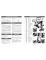
CAREFREE STANDARD SAND FILTER SYSTEM PARTS LIST
INSTALLATION INSTRUCTIONS
Item
Part No.
Description
1
425-1928
Waste Adapter Fitting
2
805-0224
O-Ring
3
830-3000
0-60 PSI Gauge
4
WVS003
Multi-Port Valve Assembly
5
505-1970
Collar Wrench
6
718-1960
Split Nut, Sand Filter
7
819-0015
Screw, 1/4" - 20 PPH x 1 1/2"
8
820-0013
Hex Nut, Serrated 1/4" - 20
9
805-0435
O-Ring
10
502-2011
Sand Fill Guide
11
505-1960
Threaded Sleeve for Split Nut
12
505-2140
16" Lateral and Manifold Assembly
505-2150
19" Lateral and Manifold Assembly
505-2160
22" Lateral and Manifold Assembly
505-2180
26" Lateral and Manifold Assembly
13
515-2101
16" Sand Filter Body
515-2091
19" Sand Filter Body
515-2081
22" Sand Filter Body
515-2121
26" Sand Filter Body
14
602-5310
Self-Threading Drain Screen
15
602-5301
Drain Cap
16
820-0017
Washer 3/8" flat
17
819-0041
Bolt 3/8" - 26" Oval Sand Filter
819-0039
Bolt 3/8" - 22" Oval Sand Filter
819-0016
Bolt 3/8" - 16" & 19" Oval Sand Filter
18
672-7241
One-Piece Base
19
429-7300
Pin & Anchor Assembly
20
PH1100
1 HP - 1-Speed - Hi-Flo Pump
PH1150
1 1/2 HP - 1-Speed - Hi-Flo Pump
PH1200
2 HP - 1-Speed - Hi-Flo Pump
PH2100
1 HP - 2-Speed - Hi-Flo Pump
PH2150
1 1/2 HP - 2-Speed - Hi-Flo Pump
PH2200
2 HP - 2-Speed - Hi-Flo Pump
21
711-4010
2" Gasket
22
319-3230
Basket Assembly (not shown)
23
319-2170
6" Pump Trap Body
24
805-0436
O-Ring
25
319-3260
6" Pump Trap Lid
26
417-6141
1 1/2" MPT x 1 1/2" Hose Male Smooth Adapter
27
872-0010
Hose Clamp, Stainless Steel
28
872-9002
Corrugated Hose, Black
29
550-1811
16" Sand Filter Hose Assembly
550-1821
19" Sand Filter Hose Assembly
550-1831
22" Sand Filter Hose Assembly
550-1833
26" Oval Sand Filter Hose Assembly
30
711-4000
1 1/2" Gasket
31
417-4161
1 1/2" Buttress x 1 1/2" MPT
32
550-1841
Return Sweep Assembly
810-0155
Instruction Sheet
DETAIL 1
DETAIL 4
DETAIL 6
DETAIL 2
DETAIL 5
DETAIL 7
DETAIL 3
1. One-piece mounting base
2. One pump
3. One filter
4. Two corrugated hoses
5. One fittings bag
6. One collar wrench
7. Trap assemblies
8. Sand filter hose assembly
NOTE
: When pressure gauge reading is 5 PSI or higher than original starting pressure,
the filter needs to be cleaned. The Carefree Standard Sand Filter System features our
exclusive 7-position multi-port valve, which ensures safe and simple filter
maintenance.
Pressurized vessel. Never attempt to loosen or open collar assembly (#6, 718-
1960 & #7, 819-0015) while system is running. It could cause severe injury
or harm to user.
NEVER CHANGE VALVE POSITION WITH PUMP RUNNING!
1. Turn off pump.
2. Attach Backwash hose (optional) to waste port adapter.
3. Rotate multi-port valve handle to
Backwash
position. Turn pump on and run for
90 second intervals or until discharge water is clear. Turn pump off.
4. Rotate multi-port valve handle to
Rinse
position. Turn pump on for 30 seconds.
5. Repeat steps 3 & 4 until all discharge water is clear while pump is turned on.
6. Rotate multi-port valve handle to
Filter
position. Turn pump on. Valve is now in
normal operating position.
1. Fill pool until water is halfway up length of skimmer throat.
2. Make sure pump trap is full of water. Slightly loosen trap lid to relieve pressure and
allow water to fill trap. Re-tighten lid.
3. Make sure multi-port valve handle is in filter position.
4. Plug pump into GFCI outlet and turn pump on. Turn two (2) speed pumps to high.
5. Make note of start-up pressure on gauge.
6. Checks for leaks.
1. Backwash filter system completely. See Cleaning Instructions.
2. Run a filter cleaning chemical through filter system as per cleaner instructions.
3. Turn pump off. Disconnect hoses from skimmer and return fitting.
4. Remove drain plug cap from bottom of filter tank.
DO NOT
remove hex drain
assembly (#14).
5. Unscrew drain plugs located at bottom of pump trap and front of pump housing.
Let water drain completely.
6. Disconnect filter to pump connection. Loosen union connection on discharge of
pump and remove from pump.
DO NOT
lose 2" union gasket. Lift and remove
pump and pump base from filter base. Store inside.
CLEANING INSTRUCTIONS
SYSTEM START UP
WINTERIZATION
10
See instructions for
proper valve alignment.
16
1
2
3
4
5
7
6
8
12
18
9
13
14
15
11
17
19
29
21
25
27
28
27
27
28
32
2
19
26
31
30
2
31
30
21
27
24
23
22
20
2
2
Optional for hard plumbing
1 ½" #7 Union Assembly - 1 ½" S Pump End
Not Included
(400-4060)
Optional for hard plumbing
1 ½" 90° Sweep Elbow - Union x Slip
Not Included
(500-1901)
19
19
21
20
5
6
7
8
9
11
11
8
4
5
7
6
9
1
2
20
21
29
24
26
25
23
22
2