Waterous Arizona Operations
500-100 & 120-P Operations
Rev 1
Page 27 of 30
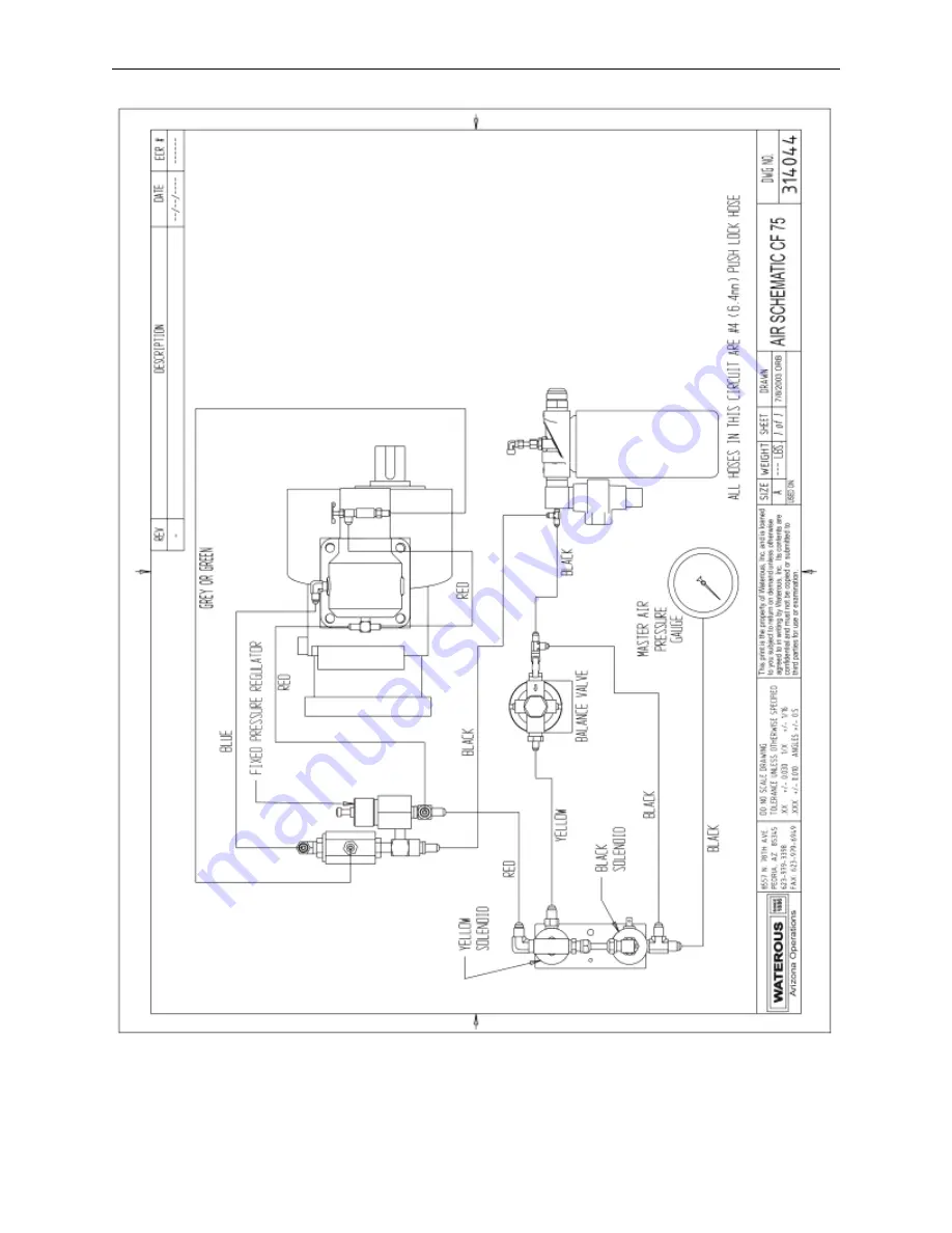
Figure 9 Air Schematic, Electric Auto-sync, 90° inlet
Page 1: ...Guide Applies to Waterous Model 500 100 P 500 120 P Rev 1 Unit Serial Number ______________________ Waterous Arizona Operations 7612 North 74th Ave Glendale Arizona 85303 623 979 3398 Fax 623 979 694...
Page 2: ...Revision History Revision Date Issued Comments 11 2005 Original Release 1 12 22 11 Reformat new logo updated pics more tables Disclaimer These instructions are guidelines only and in no way meant to...
Page 3: ...Foam Concentrate Ratios 12 C Hose 12 SECTION 5 SUGGESTED GUIDELINES FOR THE PRODUCTION OF MID RANGE COMPRESSED AIR FOAM 13 A 1 25 mm Hose Diameter Jacketed 13 B 1 1 2 38 mm Hose Diameter 13 C 1 3 4 44...
Page 4: ...ter only foam solution without compressed air compressed air foam and compressed air only for support operations such as operating air tools filling rescue air bags etc It is possible to pump foam sol...
Page 5: ...or system II Foam Solution Operations Follow the instructions above for water pumping operations Turn on the foam proportioner to inject foam concentrate into the water stream Refer to the foam propor...
Page 6: ...harge Refer to the section Suggested Guidelines for the Production of Mid Range Compressed Air Foam WARNING Nozzle reaction force is significantly increased at the time the nozzle valve is opened in c...
Page 7: ...omponents prior to operating DO NOT use the compressed air foam unit as an air source for SCBA or any breathing air supply Discharge outlets that are capped hose lines that are valved and charged and...
Page 8: ...eam is recovered by an air oil separator system This system recovers the oil mist in a spin on cartridge that has a siphon tube that picks up the recovered oil for return to the air compressor A modul...
Page 9: ...t the bottom of the sump The oil fill cap is located on top of the unit 3 Change the compressor system oil filter at the same time as the oil is changed The spin on filter cartridge is a Mann Hummel h...
Page 10: ...Daily or After Each Use X Annually X X Every 24 Months X Refer to the Engine Manual for recommended engine maintenance B Maintenance Items COMPRESSOR Part AIR FILTER CO85004 1 2030042 SEPARATOR FILTE...
Page 11: ...ssive debris or the vehicle relies on drafting for its water supply it may be necessary to install a larger strainer and or a clean out valve on the wye strainer Without good water flow through the he...
Page 12: ...B or other type foam ratio settings follow the instructions provided by the foam concentrate manufacturer C Hose Utilize fire hose that is rated by the hose manufacturer for use with CAFS Since the fo...
Page 13: ...89 5 1034 25 KPA Min Max Hose Length 35 to over 400 10 668 121 92 meters 1 GPM to 1 CFM Tip Solution Flow 20 GPM 75 71 LPM Air Flow 20 CFM 0 56 m 3 min Disch Pressure 100 150 PSI 6 804 10 206 BAR 689...
Page 14: ...68 m 3 min Disch Pressure 100 150 PSI 6 804 10 206 BAR 689 5 1034 25 KPA Min Max Hose Length 100 to over 800 30 48 243 84 meters C 1 3 4 44 mm Hose Diameter 1 GPM to 1 CFM 1 Tip Solution Flow 30 40 G...
Page 15: ...e hose The stream can also vary by changing the tip size at the nozzle The bigger the diameter tip the drier the foam The smaller the diameter tip the wetter the foam D Master Stream 1 Tip Solution Fl...
Page 16: ...solenoid and check operation of solenoid Air discharge solenoid not working Repair replace solenoid Air solenoid working leak between solenoid and discharge Repair leak Air check valve defective Repl...
Page 17: ...on level surface Excess of 200 CFM air flow on 200 CFM systems Back down RPM s and flow CAFS to relieve pressure then recheck Replace Air Oil Separator Filter Air oil Separator Filter torn or damaged...
Page 18: ...or turned too low foam tank empty Make sure proportioner is turned on foam supply valve is open foam tank has concentrate Y strainer is clean and supply line is connected to injector Discharge hose s...
Page 19: ...owing compressor to bleed down before engaging clutch again Allow for bleed down Contaminated clutch disc Clean or replace Safety pop off valve opening at low pressure Auto Sync system out of balance...
Page 20: ...and run in water until pump is completely filled and all air is expelled 4 Close discharge valve apply pressure to system and watch for leaks or overflowing water tank A pressure of 100 psi is suffici...
Page 21: ...ge valve as soon as pressure drops and prime again This procedure will usually eliminate air pockets in intake line but it may have to be repeated several times Primer not operated long enough Refer t...
Page 22: ...sible to detect liner collapse even with a light Try drafting with a new intake hose if pump then delivers capacity It may be assumed that previous hose was defective Intake hose too small When pumpin...
Page 23: ...e installation instructions have been followed Relief Valve Malfunction C Fluctuating pressure Sticky pilot valve Disassemble and clean Replace noticeably worn parts Water surges relief valve Pressure...
Page 24: ...Waterous Arizona Operations 500 100 120 P Operations Rev 1 Page 24 of 30 Figure 6 Basic CAFS Schematic...
Page 25: ...Waterous Arizona Operations 500 100 120 P Operations Rev 1 Page 25 of 30 Figure 7 500 100 P Dimensions...
Page 26: ...Waterous Arizona Operations 500 100 120 P Operations Rev 1 Page 26 of 30 Figure 8 Hydraulic Schematic...
Page 27: ...Waterous Arizona Operations 500 100 120 P Operations Rev 1 Page 27 of 30 Figure 9 Air Schematic Electric Auto sync 90 inlet...
Page 28: ...Waterous Arizona Operations 500 100 120 P Operations Rev 1 Page 28 of 30 Figure 10 Electric Schematic Auto sync...
Page 29: ...Waterous Arizona Operations 500 100 120 P Operations Rev 1 Page 29 of 30 Figure 11 Compressor Installation Angles...
Page 30: ...thereof which if assignable WATEROUS will assign to Buyer if requested by Buyer c any product or part altered modified serviced or repaired other than by WATEROUS without its prior written consent an...