background image

5

Installation Requirements

READ THIS ENTIRE INSTALLATION AND SERVICE GUIDE BEFORE BEGINNING INSTALLATION.

The Economy Reverse Osmosis (RO) Drinking Water Treatment Systems have been designed for ease of installation and
serviceability and are constructed with the finest materials available. Using these instructions and paying close attention
to the parameters outlined within "CONDITIONS FOR USE" detailed on Page 2 will ensure a successful installation.

To  ensure  a  system  continues  to  operate  at  its  optimum  level,  it  is  necessary  to  have  a  routine  maintenance  and
replacement schedule (page 16). Frequency at which filters must be changed will depend on quality of feed water supply
and level of system usage.

These  RO  systems  contain  a  replaceable  treatment  component  critical  to  the  efficiency  of  the  system.
Replacement  of  the  reverse  osmosis  component  should  be  with  one  of  identical  specification,  as  defined  by
WaterGroup  to  assure  the  same  efficiency.    Product  water  shall  be  tested  periodically  to  verify  the  system  is
performing properly.

DO NOT USE WITH WATER THAT IS MICROBIOLOGICALLY UNSAFE OR OF UNKNOWN QUALITY
WITHOUT ADEQUATE DISINFECTION BEFORE OR AFTER THE SYSTEM.

All State/Provincial and local government codes regarding installation of these devices must be observed.

Verify Water Supply is Potable

The water supply must meet provincial/state and/or national standards for potable drinking water. Water samples should
be sent to a certified laboratory for analysis.

Placement of Components

Placement of the various components of the system will vary from installation to installation. The main objective is to place
the components so that they are accessible for servicing and ease of installation. 

Do not place module where it will be exposed to freezing and/or direct sunlight.

Spigot

Proper faucet placement should ensure a no-splash waterfall pattern into the sink. The spigot handle should be positioned
to either the left or right as one faces the sink.

Storage Tank

The storage tank should be placed so that it can be easily removed from under the sink. 

Avoid placing the storage tank

in  out-of-the-way  cabinets  or  dead  spaces

.  There  are  two  reasons  for  this:  1)  the  difficulty  of  installation  increases

significantly and 2) when the storage tank is located further away from the faucet, the flow rate diminishes. 

Module Assembly

The module assembly should be hung on a sink cabinet side-wall with the two wood screws.

Quick Connect Fittings

All connections are quick connect fittings except for the compression fitting at the inlet sadle valve, drain saddle valve and
storage tank shutoff valve.

Summary of Contents for E50TFC-3NSF

Page 1: ...omy Reverse Osmosis Drinking Water System Installation Operation and Service Manual 90016 8 08 Models E50TFC 3NSF and E75TFC 3NSF are tested and certified by WQA against NSF ANSI 58 for the reduction of TDS ...

Page 2: ...sh out the preservative solution before using the system This volume of water represents approximately two days of production The water flushed should be disposed of to the drain Feed Water Quality This reverse osmosis drinking water system is not intended to be used for the treatment of water that is microbiologically unsafe or of unknown quality If the feed water quality is unsafe or unknown hav...

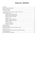
Page 3: ...embly 7 Installation of Ball Valve Assembly 8 Drilling Sink Hole 8 Installation of Non Air Gap Faucet 8 Installation of Wall Mounted Airgap 9 Installation of Filters 10 Installation of Membrane 10 Connecting Components 10 Start up Procedure 11 Maintenance Schedule 12 Sanitization Procedure for your Reverse Osmosis System 13 Maintenance Record 16 Reverse Osmosis Drinking Water System Flow Diagram a...

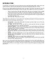
Page 4: ...rectly from the tap Ice Cubes use RO water to fill ice cube trays Ice cubes made from RO water are typically clearer and better tasting than ice made from plain tap water Automatic Ice Makers a water line from the RO system can be plumbed to refrigerators with automatic icemakers Additional accessories required to complete this connection are not included Please consult the refrigerator s owner s ...

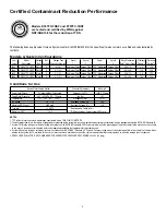
Page 5: ...ULATOR IS RECOMMENDED FOR FEED WATER PRESSURES EXCEEDING 552 kPa 80 psig Models System Configurations Conditions for Use Item Model Storage of Storage Tank Vessel Vessel Vessel Vessel Daily Production Efficiency Recovery Number Description Tank Vessels Capacity Litres gal 1 2 3 4 Rate 2 L day G day Rating 3 Rating 4 2885 RO E50TFC 3NSF Plastic 4 6 1 6 Sediment Filter Carbon Filter TFC 1 Membrane C...

Page 6: ...04 27 Tubing 1 4 OD poly red 115201 28 Airgap RO Remote Plastic 44403001 Drawing No Description Item No Membranes and Filters 10 Reverse Osmosis TFC Membrane 50 GPD TFC 92607 75 GPD TFC 92608 12 Cartridge pre filter 5 micron 26091 13 Cartridge carbon 2 each 26081 Flow Control 19 Control Flow 300ml RO 50 GPD 92610 19 Control Flow 400 ml RO 75 GPD 92611 Product Water Faucet 16 Faucet Standard 92609 ...

Page 7: ...ers out suspended particles such as dirt or sediment The filtered water then enters the pre carbon filter 3 sump models only which contains granular activated carbon which removes any chlorine from the water The water then enters the reverse osmosis membrane The membrane will allow only permeate product water to pass through The brine waste water goes to the drain Permeate then flows through a hyd...

Page 8: ...local government codes regarding installation of these devices must be observed Verify Water Supply is Potable The water supply must meet provincial state and or national standards for potable drinking water Water samples should be sent to a certified laboratory for analysis Placement of Components Placement of the various components of the system will vary from installation to installation The ma...

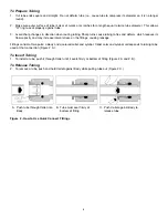
Page 9: ...pacity and may increase lateral stress on the fittings causing leakage Fittings consist of two parts a Body and a colored collet and symbol Collet color and symbol corresponds to tubing to be used at that connection Figure 2 A To Insert Tubing 1 To install a tube push it through Collet until it seats firmly at bottom of fitting Figure 2 A and 2 B To Release Tubing 2 To remove a tube push and hold ...

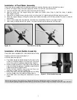
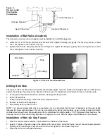
Page 10: ...r than the one serving the garbage disposal Before making a connection as shown in Figure 4 please check with code authorities Figure 4 Drain Saddle Assembly 7 Installation of Feed Water Assembly The system comes supplied with a saddle type valve with mounting hardware and is intended to be used on 3 8 to 1 2 copper tubing cold water supply line NOTE It is not to be used on flex lines a Turn off c...

Page 11: ...Remove all burrs and sharp edges e Immediately clean up the sink area NOTE If an enamel or porcelain sink is encountered it is very important that the layer of porcelain be removed before following the steps outlined above This can be accomplished by gently grinding away using a hobby grinder and silicon carbide wheel enough area of porcelain down to the metal base to accommodate a 1 1 8 high spee...

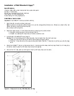
Page 12: ...to the selected location according to the surface finish a Rough or unfinished wood use two screws Item 2 b Smooth use double stick tape Item 3 Surface must be clean 3 Install Tubes onto AIRGAP body Item 4 Caution Do not use boiling water in this procedure Use hot water from the sink faucet only a Soak one end of each tube in hot water until the plastic becomes pliant b Push the tube Item 5 all th...

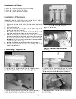
Page 13: ...b or the palm of your hand push the membrane all the way into the housing Important Do not use force and ensure that the membrane is not protruding from the housing 6 Replace the membrane housing end cap and hand tighten 7 Push the tubing back into the quick connect fitting Ensure the tubing is all the way in Connecting Components Figure 8 Installing membrane without touching Figure 7 Front View a...

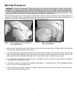
Page 14: ...ide of the Pre Carbon Filter to the Auto Shut Off Valve Direct tubing into a pail or catch basin b Turn on the feed water by opening the needle valve on the feed water saddle valve and catch the water in the pail The water rinsing the filter will appear grayish until the fines are rinsed out When the water returns to clear close the inlet water valve Re connect the white tubing back into the Auto ...

Page 15: ...ection of total dissolved solids in the water The membrane should be replaced every 24 to 36 months when its efficiency will decrease Post Carbon Filter The post filter contains a granular activated carbon Its function is to remove any taste and odor from the water prior to delivering it to the spigot The post filter cartridge should be replaced every 24 months Changing Filters Important This RO S...

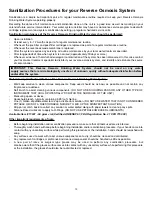
Page 16: ...onents DO NOT USE SCOURING PADS OR ANY OTHER TYPE OF INSTRUMENT THAT COULD POTENTIALLY SCRATCH THE SURFACES OF THE UNIT Measuring spoon or device Household bleach typically containing 5 25 of chlorine One 1 Gallon of potable water to mix up a disinfectant solution DO NOT USE WATER THAT IS NOT CONSIDERED POTABLE OR IS OF A QUESTIONABLE NATURE TO MIX UP THE DISINFECTANT SOLUTION Drip pan or catch ba...

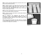
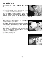
Page 17: ...ISINFECTED SURFACE Unless the membrane element is being replaced at this time then discard the old membrane STEP 4 OPEN THE FILTER SUMPS WITH THE SUMP WRENCH SUPPLIED AND REMOVE THE CARTRIDGES STEP 5 CLEAN THE FILTER SUMPS WITH SOAP AND CLEAN WATER USE A CLOTH OR SOFT BRUSH AS REQUIRED CLEAN THE INSIDE OF THE MEMBRANE HOUSING AS WELL You may need to pay close attention to the O Ring seals and re g...

Page 18: ...10 ALLOW THE SYSTEM TO SIT WITH THE DILUTED SANITIZING SOLUTION FOR APPROXIMATELY 20 MINUTES STEP 11 OPEN THE FAUCET AND PURGE THE TANK AND SYSTEM OF THE SANITIZING SOLUTION STEP 12 REINSTALL THE MEMBRANE AND REPLACE THE CARTRIDGES PURGE THE PRE CARBON CARTRIDGE OF FINES as per installation instructions OPEN THE INLET SUPPLY NEEDLE VALVE AND ALLOW SYSTEM TO FILL OPEN THE FAUCET AND DISCARD THE FIR...

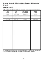
Page 19: ...WCB 10 TFC RO Membrane Procedure 5 micron Sediment Carbon Cartridge 50 or 75 USGPD refer to Cartridge Rated Membrane instructions 3 sump models 3 sump models x2 refer to model all models Every 12 months Every 24 months 24 36 months Every 6 12 months The replacement frequency of the R O membrane is somewhat dependent on the feed water quality If the product water quality has decreased or the produc...

Page 20: ...17 ...

Page 21: ...18 Reverse Osmosis Drinking Water System Flow Diagram all models ...

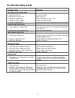
Page 22: ... feed water TDS Contact dealer for revised product water TDS 3 Membrane life expired Replace membrane Bad tasting water 1 Taste from glass or plastic containers Contact dealer for explanation 2 Post carbon filter cartridge exhausted Replace post carbon filter cartridge 3 Storage tank and or system contaminated Contact dealer for assistance 4 Membrane life expired Replace membrane Cloudy water 1 Di...

Page 23: ...20 ...
Page 24: ...part of this reverse osmosis unit because of misuse misapplication neglect alteration accident physical damage fouling and or scaling of membrane by dirt sediment minerals or bacteria attack installation or operation contrary to our printed instructions or damage caused by hot water freezing flood fire or Act of God is not covered by this warranty In all such cases regular parts and service charge...

Reviews: