WaterFurnace Envision2 Compact Installation Manual Download Page 14

14

ENVISION

2

 COMPACT - 50 HZ INSTALLATION MANUAL

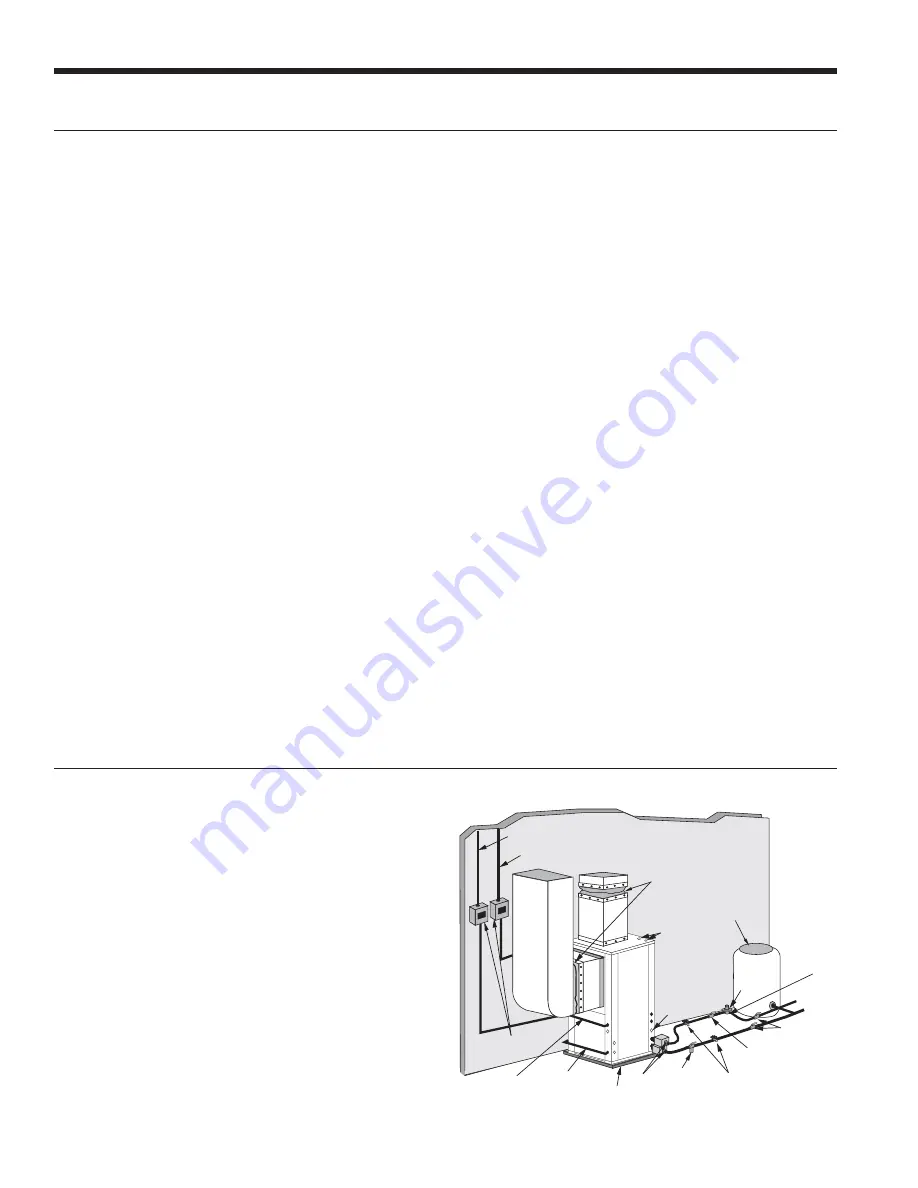
Typical open loop piping is shown below. Always maintain 

water pressure in the heat exchanger by placing water 

control valves at the outlet of the unit to prevent mineral 

precipitation. Use a closed, bladder-type expansion tank 

to minimize mineral formation due to air exposure. Insure 

proper water flow through the unit by checking pressure 

drop across the heat exchanger and comparing it to the 

figures in unit capacity data tables in the specification 

catalog. 0.09-0.13 L/s of flow per ton of cooling capacity is 

recommended in open loop applications. Due to only minor 

differences in flow rate from low to high, only one solenoid 

valve should be used. The valve should be sized for full flow. 

Discharge water from the unit is not contaminated in any 

manner and can be disposed of in various ways, depending 

on local codes, i.e. recharge well, storm sewer, drain field, 

adjacent stream or pond, etc. Most local codes forbid the use 

of sanitary sewer for disposal. Consult your local building and 

zoning departments to assure compliance in your area.

Open System - Groundwater Application

Flexible
Duct Collar

Vibration

Absorbing Pad

P/T Plugs

Drain

Hot Water Generator

Connections

Low Voltage

to Thermostat

and Valve

Unit Supply

Aux. Heat Supply

Water Out

Water In

Shut Off Valves

Boiler Drains

For HX Flushing

Disconnects

(If Applicable)

Rubber Bladder
Expansion Tank

Solenoid

Valve

Shut Off Valves

(to isolate solenoid

valve while acid flushing)

Strainer

Flow Control

Valve

(on outlet of

Solenoid Valve)

Compressor
Line Voltage

Open Loop Ground Water Systems

System Cleaning and Flushing cont.

be opened for initial flush and blowdown, making sure 

water fill valves are set at the same rate. Check the pressure 

gauge at the pump suction and manually adjust the make-

up water valve to hold the same positive pressure both 

before and after opening the drain valves. Flushing should 

continue for at least two hours, or longer if required, until 

drain water is clean and clear.

The supplemental heater and/or circulator pump, if used, 

should be shut off. All drains and vents should be opened 

to completely drain the system. Short-circuited supply and 

return runouts should now be connected to the unit supply 

and return connections.

Refill the system with clean water. Test the system water 

for acidity and treat as required to leave the water slightly 

alkaline (pH 7.5 to 8.5). The specified percentage of 

antifreeze may also be added at this time. Use commercial 

grade antifreeze designed for HVAC systems only.  

Environol™ brand antifreeze is recommended.

Once the system has been filled with clean water and 

antifreeze (if used), precautions should be taken to protect 

the system from dirty water conditions. Dirty water will 

result in system-wide degradation of performance, and 

solids may clog valves, strainers, flow regulators, etc.  

Additionally, the heat exchanger may become clogged 

which reduces compressor service life and can cause 

premature unit failure.

In boiler/tower application, set the loop control panel 

set points to desired temperatures. Supply power to all 

motors and start the circulating pumps. After full flow has 

been established through all components including the 

heat rejector (regardless of season), air vented and loop 

temperatures stabilized, each of the units will be ready for 

check, test and start up and for air and water balancing.

Ground Source Loop System Checkout

Once piping is completed between the unit pumping 

system and ground loop, final purging and charging of 

the loop is needed. A high pressure pump is needed to 

achieve adequate flow velocity in the loop to purge air 

and dirt particles from the loop itself. Antifreeze solution 

is used in most areas to prevent freezing. Flush the 

system adequately to remove as much air as possible; 

then pressurize the loop to a static pressure of 276-345 

kPa (summer) or 345-517 kPa (winter). This is normally 

adequate for good system operation. Loop static pressure 

may decrease soon after initial installation, due to pipe 

expansion and loop temperature change. Running the 

unit for at least 30 minutes after the system has been 

completely purged of air will allow for the “break-in” 

period.  It may be necessary to adjust static loop pressure 

(by adding water) after the unit has run for the first time.  

Loop static pressure will also fluctuate with the seasons.  

Pressures will be higher in the winter months than during 

the cooling season. This fluctuation is normal and should be 

considered when charging the system initially.

Ensure the pump provides adequate flow through the unit 

by checking pressure drop across the heat exchanger.  

Usually 0.14-0.19 L/s of flow per ton of cooling capacity is 

recommended in earth loop applications.

Summary of Contents for Envision2 Compact

Page 1: ...ter Piping Connections Hot Water Connections Electrical Startup Procedures Troubleshooting Preventive Maintenance COMPACT Water Source Geothermal Heat Pump 50 Hz R 410A Refrigerant Commercial 005 to 017 kW Envision 2 Compact Installation Manual ...

Page 2: ......

Page 3: ...enerator Connections 15 Freeze Detection 17 Electrical Connections 17 Electrical Data 18 Blower Performance Data 19 Wiring Schematics 21 Controls 28 Unit Startup 41 Operating Limits 42 Operating Parameters 43 Pressure Drop 44 Reference Calculations and Legend 45 Refrigerant Circuit Guideline 46 Compressor and Thermistor Resistance 46 Heat of Extraction Rejection Data 47 Troubleshooting 48 Startup ...

Page 4: ...site No Secondary Connection 1 Composite Secondary Connection 2 Stainless Steel No Secondary Connection 3 Stainless Steel Secondary Connection Air Coil Option 3 Standard 4 AlumiSealTM Filter Option A MERV 4 B MERV 13 Cabinet Option 0 Unpainted Cabinet Filter Rail 1 Painted Cabinet Filter Rail 2 Unpainted Cabinet 4 Sided Filter Rack 3 Painted Cabinet 4 Sided Filter Rack Electrical Option1 N None A ...

Page 5: ... Examine units for shipping damage removing the units from the packaging if necessary Units in question should also be internally inspected If any damage is noted the carrier should make the proper notation on the delivery receipt acknowledging the damage Safety Considerations General Installation Information Vertical Unit Mounting 50 8 mm PEX Foam Unit Location Locate the unit in an indoor area t...

Page 6: ... 6 8 7 8 7 8 6 Standard filter rails for open return applications Deluxe filter rack for ductable return applications 2 61 cm Service Access Left Return Right Return opposite side 2 61 cm Alternate Service Access Field installed duct flange ACCESS PANEL ACCESS PANEL ACCESS PANEL Front View Left Return Top View Right Return Top View Left Return P Q B R N A Front View Right Return U T C D E H F G 1 ...

Page 7: ...m 64 8 79 2 122 4 6 6 19 3 3 6 11 2 27 4 25 4 mm 22 2 mm 25 7 15 5 20 6 015 017 cm 64 8 79 2 132 6 6 6 19 3 3 6 11 2 27 4 25 4 mm 22 2 mm 25 7 15 5 20 6 6 25 12 Vertical Models Discharge Connection duct flange installed 2 54 mm Return Connection using deluxe filter rack 2 54 mm M N P Q R S T U V W Filter Rack Width Supply Width Supply Depth Return Depth Return Height 005 cm 5 6 35 6 35 6 15 5 11 4...

Page 8: ...nt Front CMP AP CMP AP AP AP AIR COIL SIDE AIR COIL SIDE 0 5 in 1 3 cm knockout 1 in 2 5 cm knockout 1 in 2 5 cm knockout 0 5 in 1 3 cm knockout BP BP FILTER RACK FILTER RACK Standard filter rails Standard filter rails Deluxe filter rack option shown Deluxe filter rack option shown Deluxe filter rack option shown B B C C L M N P L M P N A L M P N C L M C A P N D E J A 1 7 in 5 3 cm 1 7 in 5 3 cm H...

Page 9: ...0 25 4 mm 23 4 23 1 017 cm 64 8 172 7 53 8 4 6 17 3 2 0 25 4 mm 23 4 23 1 6 25 12 Horizontal Models Discharge Connection duct flange installed 2 54mm Return Connection using deluxe filter rack option 2 54 mm Unit Hanger Dimensions PVC Size L M N P Q R S T U V W X Supply Width Supply Depth Return Depth Return Height 005 cm 17 0 26 7 23 9 12 4 69 6 42 2 5 1 3 6 108 6 63 8 54 4 1 9 006 cm 17 0 26 7 2...

Page 10: ...taching the hanger rods to the bracket a double nut is required since vibration could loosen a single nut To allow filter access install hanger brackets as illustrated in the Hanger Bracket Locations section The unit should be pitched approximately 6 35 mm towards the drain in both directions to facilitate the removal of condensate Use only the bolts provided in the kit to attach hanger brackets T...

Page 11: ...36 7 71 4 62 0 n a 015 99S500A04 157 0 71 4 62 0 n a 017 99S500A03 174 8 71 4 62 0 74 4 Dimensions are listed in cm 6 25 12 Weight Distribution Model Vertical Weight Horizontal Weight Horizontal Weight Distribution Front Back D E F G 005 95 100 29 18 32 16 006 127 134 34 31 34 13 009 163 170 52 43 34 27 012 168 172 54 45 36 29 015 186 191 54 50 43 36 017 202 206 61 54 45 39 Weights are listed in k...

Page 12: ...nit whenever the unit operates To assure proper flow use pressure temperature ports to determine the flow rate These ports should be located at the supply and return water connections on the unit The proper flow rate cannot be accurately set without measuring the water pressure drop through the refrigerant to water heat exchanger All source water connections on commercial units are fittings that a...

Page 13: ...bove this level deposition will occur Less than 1 ppm above this level deposition will occur Less than 1 ppm above this level deposition will occur Erosion Suspended Solids Less than 10 ppm and filtered for max of 600 micron size Less than 10 ppm and filtered for max of 600 micron size Less than 10 ppm and filtered for max of 600 micron size Threshold Velocity Fresh Water 1 8 m sec 1 8 m sec 1 8 m...

Page 14: ...Refill the system with clean water Test the system water for acidity and treat as required to leave the water slightly alkaline pH 7 5 to 8 5 The specified percentage of antifreeze may also be added at this time Use commercial grade antifreeze designed for HVAC systems only Environol brand antifreeze is recommended Once the system has been filled with clean water and antifreeze if used precautions...

Page 15: ...rs 3 Close the cold water inlet valve to the water heater tank 4 Drain the tank by opening the valve on the bottom of the tank then open the pressure relief valve or hot water faucet 5 Flush the tank by opening the cold water inlet valve to the water heater to free the tank of sediments Close when draining water is clear 6 Disconnect the garden hose and remove the drain valve from the water heater...

Page 16: ...rical supply to the water heater adjust the temperature setting on the tank On tanks with both upper and lower elements the lower element should be turned down to the lowest setting approximately 37 8 C The upper element should be adjusted to 48 9 C to 54 4 C Depending upon the specific needs of the customer you may want to adjust the upper element differently On tanks with a single element lower ...

Page 17: ... codes or the National Electric Code whichever is applicable Power Connection Connect the incoming line voltage wires to L1 and L2 of the contactor for single phase unit Consult the Electrical Data tables for correct fuse sizes Electrical Connections For Aurora Base Control set SW2 1 FP1 on the printed circuit board for applications using a closed loop antifreeze solution to 9 4 C On applications ...

Page 18: ... 30 9 4 0 10 9 12 6 15 HACR circuit breaker in USA only With optional IntelliStart 5 21 13 Variable Speed ECM Motor Model Rated Voltage Voltage Min Max Compressor Blower Motor FLA Total Unit FLA Min Circ Amp Max Fuse HACR Breaker MCC RLA LRA LRA Single Speed 005 220 240 50 1 198 264 13 1 5 5 24 0 9 6 4 0 9 5 10 9 15 017 220 240 50 1 198 264 38 2 24 5 153 0 61 2 7 0 31 5 37 6 60 380 420 50 3 342 46...

Page 19: ...70 363 356 347 342 335 326 316 309 304 288 257 Low 1 G 335 323 314 307 300 290 283 276 269 250 234 224 009 High 5 W 279 x 254 0 37 743 729 720 706 696 684 675 663 656 644 635 616 590 569 538 465 Med High 4 Y2 710 689 668 658 649 637 625 611 599 588 578 555 538 498 465 Med 3 Y1 694 668 644 621 604 592 583 573 564 550 538 512 484 420 Med Low 2 687 661 635 606 590 578 569 555 543 531 522 493 465 427 ...

Page 20: ... Aux can be adjusted directly at the Aurora ABC board which utilizes the push button SW1 on the ABC board This procedure is outlined in the variable speed ECM Configuration Mode portion of the Aurora Base Control System section Variable Speed ECM Setup with an AID Tool A much easier method utilizes the AID Tool to change the airflow using the procedure below First navigate to the Setup screen and ...

Page 21: ...on Options NET NET COM NET NET COM 1 2 1 2 LON Network Connections Devices Must Be Wired in Daisy Chain Configuration Page 1 DIP Switch Value 1 2 4 8 ON 1 2 3 4 ZS Sensor Information Each ZS sensor must have a unique address but the addresses do not need to be sequential Use the DIP switches on the back of the ZS sensor to set an address from 0 to 4 0 is the factory default Each DIP switch has the...

Page 22: ...upply 380 420 50 3 G Green 93 Red 97 1 2 3 L N G X13 Fan Motor C 4 5 Green Orange Brown Tan Gray Blue Red Black Black White Black White Yellow Note 5 UltraTech Dual Capacity Units Only RCP CS Blue 16 Blue 18 CFM P13 P4 SW1 P5 JW2 P9 LO O B Y2 W DH P8 P7 RS485 NET RS485 NET P6 RS485 EXP P3 SW2 On Future Use L Output Type CC Dual Single Acc Dip 5 Acc Dip 4 RV B O FP2 15 F 30 F FP1 15 F 30 F Com1 LED...

Page 23: ...Terminal Field Wiring Lug Ground Relay Contacts N O N C Field Zone Sensor Wiring Legend L1 Capacitor T 1 2 3 CC Compressor Contactor CO Condensate Overflow Sensor ES Emergency Shutdown HP High Pressure Switch LP Low Pressure Switch FD Freeze Detection Sensor F1 Fuse Fuse Light Emitting Diode Green G Light Emitting Diode Yellow Y Light Emitting Diode Red R SW1 Push button SW2 DIP package 8 position...

Page 24: ...7 1 2 3 L N G X13 Fan Motor C 4 5 Green Orange Brown Tan Gray Blue Red Black Black White Black White Yellow Note 5 UltraTech Dual Capacity Units Only RCP CS Blue 16 Blue 18 Red 380V NOTE 6 CFM P13 P4 SW1 P5 JW2 P9 LO O B Y2 W DH P8 P7 RS485 NET RS485 NET P6 RS485 EXP P3 SW2 On Future Use L Output Type CC Dual Single Acc Dip 5 Acc Dip 4 RV B O FP2 15 F 30 F FP1 15 F 30 F Com1 LED5 Com2 LED5 Test Mo...

Page 25: ... Lug Ground Relay Contacts N O N C Field Zone Sensor Wiring Legend L1 Capacitor T 1 2 3 CC Compressor Contactor CO Condensate Overflow Sensor ES Emergency Shutdown HP High Pressure Switch LP Low Pressure Switch FD Freeze Detection Sensor F1 Fuse Fuse Light Emitting Diode Green G Light Emitting Diode Yellow Y Light Emitting Diode Red R SW1 Push button SW2 DIP package 8 position RB Blower Relay RV R...

Page 26: ...Yellow 96 Red 97 Gray 94 Brown Orange Red 56 Blue 55 Black 54 Red 56 Blue 55 Black 54 CC 470 470 Resistor Violet 14 Black 15 Orange 01 Orange 02 Condensate Brown 23 Green RV HP LP T FD RV Blue 07 Blue 08 Black 09 Black 10 Yellow Yellow UltraTech Dual Capacity Units Only RCP CS Blue 16 Blue 18 Red 380V NOTE 5 CFM P13 P4 SW1 P5 JW2 P9 LO O B Y2 W DH P8 P7 RS485 NET RS485 NET P6 RS485 EXP P3 SW2 On F...

Page 27: ...elay High Pressure Start Up Bypass Low Pressure Fault Recognition Delay Low Pressure Start Up Bypass Low Water Air Coil Limit Fault Recognition Delay Low Water Air Coil Limit Fault Recognition Delay Condensate Overflow Thermostat Call Recognition Time Auxiliary Heat Staging Delay Emergency Heat Staging Delay Less than 1 second 5 to 80 seconds 1 second 5 seconds 1 second 30 seconds 2 seconds Less t...

Page 28: ...ff Additionally when entering test mode LED1 red will flash the last lockout one time Test mode will automatically time out after 30 minutes Test mode can be exited by pressing and holding the SW1 button for 2 to 5 seconds or by cycling the power Test mode will automatically be exited after 30 minutes Variable Speed ECM Configuration Mode The control is placed in variable speed ECM configuration m...

Page 29: ...on the control will stage off the outputs and then try again to satisfy the thermostat Y input call Once the thermostat input calls are satisfied the control will continue on as if no fault occurred If 3 consecutive faults occur without satisfying the thermostat Y input call then the control will go to Lockout mode Lockout when locked out the blower will operate continuously in low speed and PSC b...

Page 30: ...st stage of electric heat will be turned on 5 seconds after the first stage of electric heat is energized the blower will shift to high speed If the emergency heat demand is not satisfied after 2 minutes the second electric heat stage will be energized Blower G The blower will start immediately upon receiving a thermostat G command If there are no other commands from the thermostat the variable sp...

Page 31: ...ze Detection 1 Coax Flash Code 5 Reserved Flash Code 6 Condensate Overflow Flash Code 7 Over Under Voltage Shutdown Flash Code 8 Freeze Detection Sensor Error Sensor is Out of Range Flash Code 11 Aurora Interface and Design AID Tool The Aurora Interface and Diagnostics AID Tool is a device that is a member of the Aurora network The AID Tool is used to troubleshoot equipment which uses the Aurora c...

Page 32: ... into our latest water source heat pumps This will allow for a BAS to integrate and communicate to the heat pump thru a choice of 3 different communication protocols The Aurora UPC has the ability to communicate BACnet MS TP N2 open or LonWorks requires LON Plugin card This flexibility is possible due to the onboard dipswitches which allow for the desired protocol and baud rate to be selected in t...

Page 33: ...ling control from a remotely located zone sensor Rnet communication port which allows for multiple Rnet zone sensors 5 to be connected for space temperature averaging if desired Local laptop or BACview connection for field service FCC UL and CE listed BTL Certification is pending N2 BACnet LonWorks BAS Rnet Modbus Aurora UPC Optional Features BACview handheld display needed for field configuration...

Page 34: ...ud rate for the BAS port Mac address is set by 2 rotary dials Aurora Touch Interface Utilizing a touch screen interface the UPC provides a technician the ability to configure and diagnose equipment at the unit or from any room sensor for added accessibility and simpler troubleshooting The technician will have full access to equipment status parameter values temperature and humidity sensing as well...

Page 35: ...s sec Fault Freeze Detection FP1 5 Yes Hard or Soft Freeze protection sensor has tripped 15 or 30 degF for 30 continuous sec Fault Condensate Overflow 7 Yes Hard or Soft Condensate switch has shown continuity for 30 continuous sec Fault Over Under Voltage 8 No Auto Instantaneous voltage is out of range Controls shut down until resolved Fault FP1 2 Snsr Error 11 Yes Hard or Soft If FP1 or 2 Sensor ...

Page 36: ...1 A configurable accessory relay on the ABC is provided that can be cycled with the compressor blower or the Dehumidifier DH input A third factory setting cycles the relay with the compressor but delays the compressor and blower output for 90 sec Source pump or slow opening solenoid valves in well systems or variable speed primary pumping systems would be a prime use of this feature Access Relay O...

Page 37: ...rovided to optionally drive a modulating water valve Through ad vanced design a 0 10VDC valve can be driven directly from the VS pump output The minimum and maxi mum level are set in the same way as the VS pump using the AID Tool 75 and 100 are the default set tings respectively 4 Loop Pump Slaving This input and output are pro vided so that two units can be slaved together with a common flow cent...

Page 38: ...g cooling liquid line FP1 These sensors allow the measurement of discharge and suction pressures suction and liquid line temperatures as well as superheat and subcooling This information can be displayed on the BACview Tool or the network when using BACnet and N2 Htg Liquid Line Clg Liquid Line Discharge pressure Suction Pressure Discharge Saturated Temp Suction Saturated Temperature Superheat Sub...

Page 39: ...ne ZS Pro or ZS Pro F with up to four ZS standard sensors wired to the Rnet port on the UPC for a total of 5 zone sensors The sensors use a precise 10k ohm thermistor with less than 0 18 F drift over a ten year span this allows for less maintenance or re calibration after installation The sensors also have a hidden communication port for connecting a BACview or local laptop that provides access to...

Page 40: ...le Temp with VOC or Temp VOC Humidity All Models 12 Vdc 60 mA Temp with CO2 or Temp CO2 Humidity All Models 12 Vdc 15 mA idle to 190 mA CO2 measurement cycle Power Supply A controller supplies the Rnet sensor network with 12 Vdc 210 mA Additional power may be required for your application See sensor ZS Installation Guide Communication 115 kbps Rnet connection between sensor s and controller 15 sen...

Page 41: ...low rate is correct by measuring the pressure drop through the heat exchanger using the P T plugs and comparing to the pressure drop table 6 Check the temperature of both the supply and discharge water Refer to Operating Parameters tables 7 Check for an air temperature drop of 8 3 C to 13 9 C across the air coil depending on the blower speed and entering water temperature 8 Decrease the cooling se...

Page 42: ...93 2068 2310 6 9 2 6 4 6 13 17 21 1 0 09 896 1000 2206 2448 7 11 2 6 6 8 17 20 0 19 931 1034 2241 2482 7 11 2 6 4 7 18 21 32 2 0 09 1034 1103 2413 2689 7 11 2 6 6 8 17 20 0 19 1069 1038 2517 2792 7 11 2 6 4 7 18 21 43 3 0 09 0 19 NOTE Cooling performance based on entering air temperatures of 26 7 C DB 67 C WB Heating performance based on entering air temperature of 21 1 C DB 6 25 12 Operating Limi...

Page 43: ... performance based on entering air temperatures of 26 7 C DB 67 C WB Heating performance based on entering air temperature of 21 1 C DB 6 25 12 Second Stage Operation Entering Water Temp C Water Flow L s per kW Cooling No Hot Water Generation Suction Pressure kPa Discharge Pressure kPa Superheat Subcooling Water Temp Rise C Air Temp Drop C DB 1 1 0 09 793 862 1034 1172 11 19 6 9 6 11 5 7 0 19 724 ...

Page 44: ...9 3 4 0 32 10 4 1 61 0 44 15 2 14 5 13 1 12 4 11 7 0 44 10 8 2 90 0 57 23 4 22 1 20 7 19 3 17 9 0 57 11 2 4 43 0 69 33 8 31 7 29 6 27 6 25 5 0 76 11 9 7 03 012 0 38 8 3 8 3 7 6 6 9 6 9 1 0 38 16 1 0 96 0 57 16 5 15 2 14 5 13 8 12 4 0 57 16 8 1 99 0 76 26 9 24 8 23 4 22 1 20 0 0 76 17 4 3 27 0 95 39 3 36 5 34 5 32 4 29 6 0 95 18 1 4 76 015 0 50 12 4 11 7 11 0 9 7 9 0 1 0 57 16 8 1 99 0 76 26 2 24 1...

Page 45: ...eat pump FLA full load amps FtHd pressure drop in feet of head gpm US gallon per minute HC heating capacity in kW HE heat of extraction in kW HR heat rejected in kW kPa kilopascal kW kilowatt L s liters per second LLT leaving load fluid temperature from heat pump LRA locked rotor amps starting current LST leaving source fluid temperature from heat pump LWPD load heat exchanger water pressure drop ...

Page 46: ...h Normal Low Normal Low Air Flow Heating High High High High Normal Low High Low Low Air Flow Cooling Low Low Low Low Normal High High Low Low Water Flow Heating Low Normal Low Normal Low Low High Low High Low Water Flow Cooling High High High High Low Low High High Air Flow Heating Low Low Low Low High Low Low High Air Flow Cooling Low High Normal High Low Low Normal High Water Flow Heating Norma...

Page 47: ...9 0 Full Load 0 32 7 36 9 20 10 52 14 16 14 21 13 4 0 44 5 51 7 68 9 70 11 25 13 2 14 30 14 42 13 7 12 8 0 57 5 63 7 88 9 99 11 63 13 3 14 39 14 54 13 8 12 8 012 Part Load 0 32 6 80 8 38 9 58 13 89 14 21 13 5 0 50 5 39 7 50 9 29 10 70 12 6 13 92 14 16 13 4 12 4 0 69 5 60 7 80 9 79 11 40 12 4 13 92 14 27 13 6 12 7 Full Load 0 38 9 82 11 96 13 54 18 58 18 52 17 3 0 57 7 65 10 20 12 60 14 45 17 3 18 ...

Page 48: ...k the reversing valve coil If the unit operation is noisy 1 Check compressor for loosened mounting bolts Make sure compressor is floating free on its isolator mounts Check for tubing contact with the compressor or other surfaces Readjust it by bending slightly 2 Check screws on all panels 3 Check for chattering or humming in the contactor or relays due to low voltage or a defective holding coil Re...

Page 49: ...__ VOLTS m ______ VOLTS Total Amps Comp Fan n _____ AMPS n ______ AMPS n ______ AMPS Watts m x n x 0 85 o _____ WATTS o ______ WATTS o ______ WATTS 6 CAPACITY Cooling Capacity HR o p _____ kW hr Heating Capacity HE o p _____ kW hr 7 EFFICIENCY Cooling EER p o q _____ COP Heating COP p o q _____ COP 8 SUPERHEAT S H SUBCOOLING S C COOLING HEATING HYDRONIC Suction Pressure r ______ kPa r ______ kPa r...

Page 50: ...re kPa Entering Load Water C Entering Load Water Pressure kPa Leaving Load Water C Leaving Load Water Pressure kPa Load Coax Suction Discharge Compressor RV Source Coax FD ______kPa ______SAT C ______ C ______kPa ______SAT C ______ C ______ C Liquid Line Load Coax Unit Amp Draw Line Voltage Loop Open Closed Subcooling Superheat NOTE Do not attach refrigerant gauges unless a problem is suspected En...

Page 51: ...ever be operated without a filter Condensate Drain In areas where airborne bacteria produce a slime in the drain pan it may be necessary to treat chemically to minimize the problem The condensate drain can pick up lint and dirt especially with dirty filters Inspect twice a year to avoid the possibility of overflow Blower Motors Blower motors are equipped with sealed ball bearings and require no pe...

Page 52: ... HWL Thermistor 12P505B02 12P505B02 High Pressure Switch 35P506B02 35P506B02 Low Pressure Switch 35P506B01 35P506B01 Part numbers subject to change 04 21 14 Part Description Single Speed Horizontal Units Dual Capacity Horizontal Units 005 017 006 009 012 015 Compressor Compressor 220 240 50 1 34P593 03 34P561 09 34P640 02 34P641 02 34P642 02 34P643 01 Compressor 380 420 50 3 N A 34P646 04 34P640 0...

Page 53: ...on 19 Jan 2015 MA All Updated with All Aluminum Air Coils 21 May 2014 DS 18 Updated Compressor LRA with IntelliStart 31 Jul 2013 DS All Updated Nomenclature to Reflect new ECM Blower Motor 06 Nov 2012 DS 46 Updated Service Parts List for New ECM Blower Part Numbers 06 Nov 2012 DS 47 Added Revision Guide 06 Nov 2012 DS ...

Page 54: ...al Inc 9000 Conservation Way Fort Wayne IN 46809 9794 WaterFurnace has a policy of continual product research and development and reserves the right to change design and specifications without notice Product Envision2 Compact Type Water Source Geothermal Heat Pump 50 Hz Size Commercial 005 017 kW Document Installation Manual IM1022AN 01 15 ...

Reviews: