25
activities, including triggering a relay device, sending an alert to a security office
or storing pre-alarm video to the DVR.
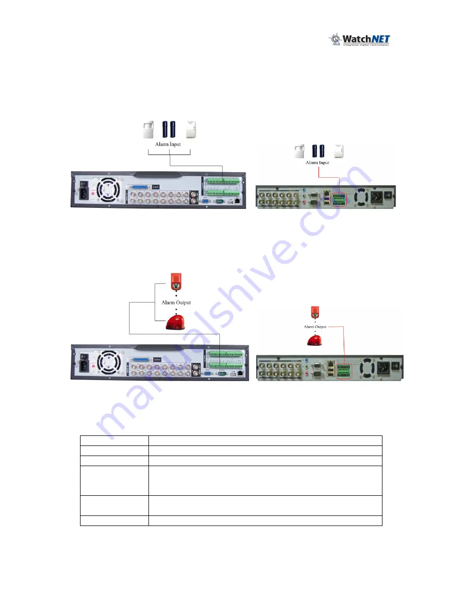
3.7.5 Alarm Input
Check the alarm input mode if it is grounding alarm input or not. For this series
DVR, grounding signal is needed for alarm input. If connecting two units or one
DVR and other device, please use a relay to separate them. Please refer to
372H
Figure 3-6 for more information.
Figure 3-6
3.7.6 Alarm Output
Do not connect alarm output port directly with high power load (no more than 1 A)
in case of heavy current. Use the co-contactor to utilize the connection between
the alarm output port and the load. Please refer to
373H
Figure 3-7 for more information.
Figure 3-7
3.7.7 Alarm Input and Output Details
Refer to the following sheet and
374H
Figure 3-8 for alarm input and output
information.
Parameter
Grounding Alarm
Ground
Ground line
Alarm Input
1, 2, …, 16
Relay Output
1,2,3,4: NO and C(Normally Open and Com)
5: NO,C and NC(Normally Open, Com, Normally Closed)
6: Ctrl 12V(This is used for reset the sensor)
RS-485 A & B
RS-485 communication port. They are used to control
devices such as a PTZ. camera
+12v & C
This should input an external power input.
•
4/8/16-ch grounding alarm inputs. (Normally open or Normally close type)
•
Please parallel connect COM end and GND end of the alarm detector (Provide
external power to the alarm detector)
Summary of Contents for RTS series
Page 1: ......
Page 61: ...61 Figure 5 378...


