background image

Hardware Specifications

4

Hardware Description

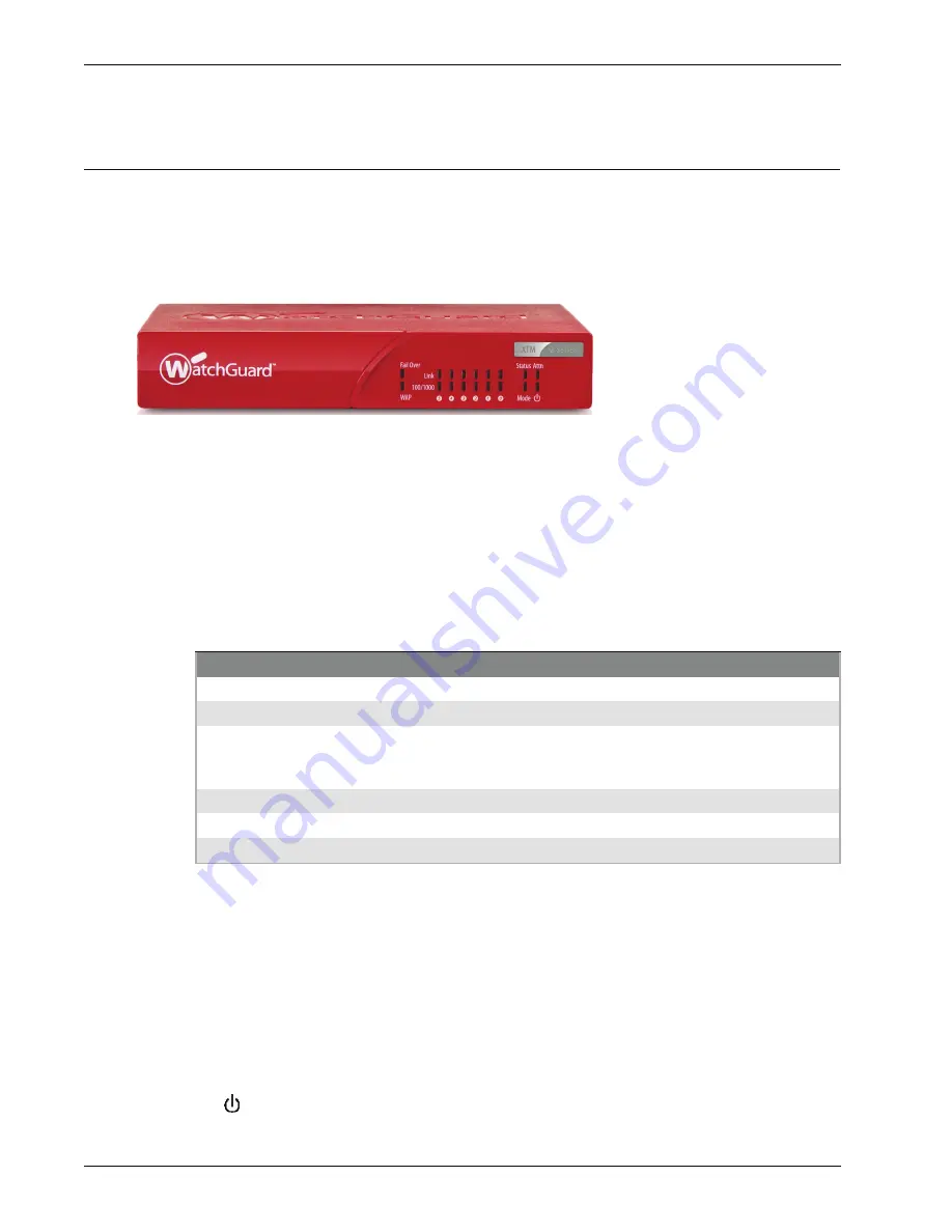
All indicator lights are on the front panel of the device, and all ports and connectors are on the rear panel. 

Front view

The front panel of the device.

Fail Over

The Fail Over indicator is green when there is a WAN failover from the primary external interface to 
the backup interface. After the external interface connection fails back to the primary external 
interface the indicator is not lit. 

WAP

The WAP indicator is green when an XTM 2-Series wireless device is activated as a wireless access 
point. The light is green when traffic goes through the wireless interface.

Network interface status indicators

The status indicators for the six network interfaces are labeled 5, 4, 3, 2, 1, 0. There are two status 
indicators for each interface.

Status

The Status indicator shows when there is a management connection to the device. When you use 
your browser to connect to the Fireware XTM Web UI, the indicator is lit. The Status indicator is unlit 
a short time after you log out of the Fireware XTM Web UI or close your browser. 

Mode

The mode indicator shows the status of the external network connection. If the device can connect 
to the external network and send traffic, the indicator is green. The indicator flashes if the device 
cannot connect to the external network and send traffic.

Attn

The Attn indicator is lit when you reset the device to factory default settings.

Power (

)

The power indicator is lit when the device is on.

Indicator

Indicator color

Interface Status

Link

Green

Power on, connection established

Not lit

Power off, no connections

Blinks
(speed of blink increases as the 
data flow increases)

Data sent and received

100/1000

Not lit

Operates at 10 Mbps

Green

Operates at 100 Mbps

Yellow

Operates at 1000 Mbps

Summary of Contents for XTM 2 Series

Page 1: ...WatchGuard XTM 2 Series Hardware Guide XTM 21 22 23 21 W 22 W 23 W...

Page 2: ...ion please call 206 613 6600 or visit www watchguard com Copyright and Patent Information Copyright 1998 2009 WatchGuard Technologies Inc All rights reserved WatchGuard the WatchGuard logo Firebox Liv...

Page 3: ...reby release WatchGuard from any liability for performance of enforcement of or damages or other relief on account of any such warranties or any breach thereof 2 REMEDIES If any Product does not compl...

Page 4: ...1980 United Nations Convention on Contracts for the International Sales of Goods as amended shall not apply You agree not to directly or indirectly transfer the Product or use of the product or associ...

Page 5: ...ow Voltage 2006 95 EC Electromagnetic Compatibility 2004 108 EC Common Standard s EN60950 1 2001 Safety of ITE valid until 2010 12 01 EN50022 2006 Class A Emissions for ITE EN61000 3 2 2000 W A2 05 Ha...

Page 6: ...nges or modifications to ANY PART OF THIS PRODUCT not expressly approved by WatchGuard could void the user s authority to operate the equipment per FCC regulations In particular modifying antenna gain...

Page 7: ...r p is not more than that permitted for successful communication Frequency band from 5 15 GHz to 5 25 GHz is restricted to indoor use only to reduce potential for harmful interference to co channel mo...

Page 8: ...only on channels 10 11 12 13 as defined by IEEE 802 11g b Use of the product outdoors or on any other channel is illegal in France RoHS Statement The member states of the European Union approved direc...

Page 9: ...policy REACH Registration Evaluation Authorization and restriction of Chemicals came into effect on June 1 2007 REACH is Europe s new chemicals legislation which is applicable in all 27 EU Member Stat...

Page 10: ...anklin Street Fifth Floor Boston MA 02110 1301 USA Everyone is permitted to copy and distribute verbatim copies of this license document but changing it is not allowed Preamble The licenses for most s...

Page 11: ...fter translation is included without limitation in the term modification Each licensee is addressed as you Activities other than copying distribution and modification are not covered by this License t...

Page 12: ...he terms of Sections 1 and 2 above on a medium customarily used for software interchange or Accompany it with the information you received as to the offer to distribute corresponding source code This...

Page 13: ...lling to distribute software through any other system and a licensee cannot impose that choice This section is intended to make thoroughly clear what is believed to be a consequence of the rest of thi...

Page 14: ...OR AGREED TO IN WRITING WILL ANY COPYRIGHT HOLDER OR ANY OTHER PARTY WHO MAY MODIFY AND OR REDISTRIBUTE THE PROGRAM AS PERMITTED ABOVE BE LIABLE TO YOU FOR DAMAGES INCLUDING ANY GENERAL SPECIAL INCIDE...

Page 15: ...ware products offered by WatchGuard XTM 2 Series The WatchGuard XTM 2 Series is a network security device for small organizations and branch offices The XTM 2 Series product line includes WatchGuard X...

Page 16: ...or the bottom of the device 1 straight through Ethernet cable 1 Wall mount plate wireless models only Three antennas wireless models only About Your Hardware Hardware specifications Interface Specific...

Page 17: ...eople who do not have permission to use it Connect it to a conditioned power supply to prevent damage from sudden power changes Other environmental requirements for the XTM 2 Series units Operating te...

Page 18: ...ce Status The Status indicator shows when there is a management connection to the device When you use your browser to connect to the Fireware XTM Web UI the indicator is lit The Status indicator is un...

Page 19: ...evice and to a power source The power supply tip is plus polarity RESET button To reset the device use the procedure in Restore Factory Default Settings on page 10 USB interfaces The two USB interface...

Page 20: ...e AC power adapter does not match your power source 1 Use your thumb or finger to move the locking key on the AC power adapter down 2 Hold the bottom of the plug 3 Pull up from the bottom of the plug...

Page 21: ...n on the back of the device 3 Connect the power supply while you continue to hold down the Reset button 4 Continue to hold down the button until the yellow Attn indicator stays lit This shows that the...

Page 22: ...to the receiver must move along more than one path because of walls and other surfaces between the transmitter and the receiver It changes based on the phase at which the signals come Signal strength...

Reviews: