background image

WARMBOARD COMFORT SYSTEM  //  GAS

10

Manifold Cabinet

PREPARATION

Before installing the controls, an electrician 

MUST


review the electrical page of the WCS Design 
Drawings and note necessary materials, locations, 
voltage and amperage of all electrical components.


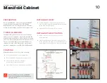
TUBING & LABELING

Included with your controls is a series of labels to 
adhere to each supply and return loop beneath the 
manifold. Appropriate use of these labels will ensure 
each loop is accurately labeled for diagnostic issues. 
These color-coded labels coincide with the color 
labels on the side of the Manifold Controller (MC) 
and those displayed in your WCS Design Drawings.


CONTROLS

Warmboard Controls consist of the following: 


f

120 volt thermostats (one per heating zone)   


f

120 volt Manifold Controller (one per manifold)


f

24 volt solenoid valve loop actuators  
(one per loop, powered by the MC)


f

Smart Reset Controller (inside Warmsource-N/P) 


INSTALLING THE MC


f

Use the provided screws to mount each Manifold 
Controller (MC) inside the manifold cabinet specified 
by the WCS Design Drawings


f

Plug the MC into the nearby 120 volt outlet


INSTALLING THE ACTUATORS


f

Attach an actuator to each return port on the  
return manifold


f

Connect each actuator wire to the appropriate port 
on the side of the MC, which is pre-labeled and color 
coded. Refer to the WCS Design Drawings as needed

Before installing the controls, you 

MUST


disable Construction Mode by removing the 
jumper on the SRC.

Summary of Contents for Warmsource-N

Page 1: ...1 1 800 556 0595 for assistance FOR USE WITH Warmsource N natural gas boiler Warmsource P propane gas boiler Warmboard Comfort System INSTALLATION GUIDE 1021...

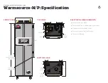
Page 2: ...e exhaust gas vent is required 7 The constant pressure circulation pump s inside Warmsource N P adjust flow rates depending on the needs of each zone 8 Once system plumbing is complete test the system...

Page 3: ...and WCS f Foundation and joist f Install Warmboard S f Install tubing some loops before walls f Frame walls roof sheeting f Install tubing manifolds some loops f Install all 120 volt electrical boxes...

Page 4: ...red by code in many jurisdictions it prevents water in the closed loop system from mixing with the domestic water f Air purging valves a 1 1 4 combo ball valve hose bib along with several smaller valv...

Page 5: ...ibution lines for 15 minutes at 100 PSI International Mechanical Code section 1208 1 MINIMUM CLEARANCES This illustration shows the recommended minimum dimensions for the Warmsource N P mechanical are...

Page 6: ...301 2 56 11 4 Brass Union supply 11 4 Brass Union return 3 Air Intake T P Relief Valve 3 Exhaust 53 4 57 8 6 3 4 Gas line left side preferred right side OK Condensation Discharge Line 361 2 171 2 21 2...

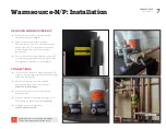
Page 7: ...cket the unit weighs 150lbs and requires two individuals to move safely CONNECTIONS f Connect the PVC intake and exhaust lines gas line condensation discharge line and T P relief discharge line per th...

Page 8: ...ng the system with water for 10 15 minutes until air cannot be seen or heard escaping the hose f Close the fast fill lever then slowly close hose bib A f Ensure the pressure gauge located inside Warms...

Page 9: ...p 3 Plug Warmsource N P into the 120 volt outlet and confirm the system is ON using the rocker switch and power button circled in the photo to the right Warmsource N P will reach the target temperatur...

Page 10: ...sign Drawings CONTROLS Warmboard Controls consist of the following f 120 volt thermostats one per heating zone f 120 volt Manifold Controller one per manifold f 24 volt solenoid valve loop actuators o...

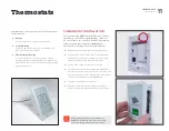
Page 11: ...inaccurately If there are any discrepancies regarding the thermostat or zoning contact us immediately f Remove the appropriate thermostat from the box f Grip the face of the thermostat on the sides w...

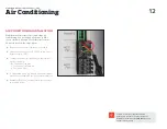
Page 12: ...rminal connection AC1 Fan on the Smart Reset Controller SRC f Connect the wires from the AC unit to the terminal block accordingly RC 24v power red wire Y Cooling Call yellow wire G Fan green wire f T...

Page 13: ...inutes the green lights will turn blue indicating that the actuators have opened and water is flowing to the zone f If something does not appear to be working properly consult your Warmboard Engineere...

Page 14: ...E ARE EXPRESSLY EXCLUDED FAILURE TO INSTALL WARMBOARD PRODUCTS ACCORDING TO MANUFACTURER S INSTRUCTIONS WILL VOID ALL APPLICABLE WARRANTIES IT IS EXPRESSLY UNDERSTOOD THAT WARMBOARD IS NOT RESPONSIBLE...

Reviews: