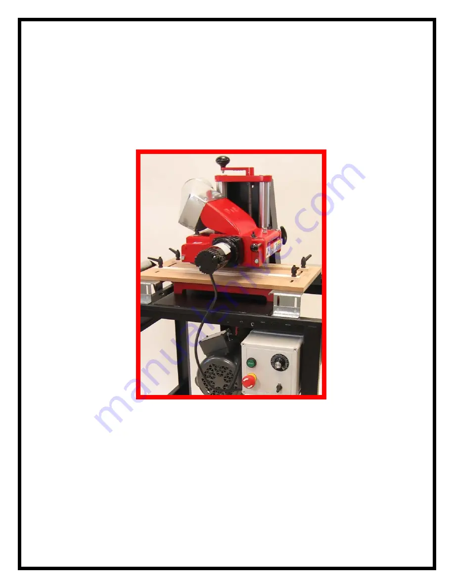
W&H MODEL 206 MOLDER OWNERS MANUAL WILLIAMS & HUSSEY MACHINE CO. www.williamsnhussey.com
Page 1: ...W H MODEL 206 MOLDER OWNERS MANUAL WILLIAMS HUSSEY MACHINE CO www williamsnhussey com...
Page 2: ...re Knife changing is so simple that it can be perfectly done in about two minutes allowing you to quickly move from job to job The machine is manufactured in New Hampshire by people who take pride in...
Page 3: ...lation 12 13 Guide system GS1 operation 14 16 Guides 26 27 Knife changing installation 22 Knife sharpening 23 Machine parts illustration 39 Molding 24 25 Parts list 35 36 Picture frames 27 Planing 31...
Page 4: ...re 1 10 screws and lock washers 2 2 x 5 8 round head screws 15 3 lock washers 19 4 nuts 12 5 flat washers 3 6 x 1 hex head bolts 4 7 5 16 x bolts nuts flat washers and lock washers 4 8 3 8 x 2 axle bo...
Page 5: ...Insert the 3 8 x 2 axle bolts through the holes provided Install the flat washer lock washer nut and tighten Install brake knobs in threaded insert on end of the stand Mount castor wheel on its base...
Page 6: ...and nuts Do not tighten yet The motor is mounted with the shaft end in line with the cut out for the belt in the machine mounting area Mount the pulley on the motor shaft Place the machine on the stan...
Page 7: ...Bolt the machine base to the stand using 4 x 1 long hex head bolts and lock washers Use the nuts that held the machine to its shipping pallet 6 Install the belt from the machine to the motor...
Page 8: ...e bed of the machine Align the belt so that the belt travels in a straight line from one pulley to the other Install the belt guard bracket Use 2 10 24 x screws and lock washers 7 Take the belt guard...
Page 9: ...ighten all three guard screws Mount the vertical roller support brackets in pairs left and right hand on both ends of the stand Use x 5 8 long round head screws lock washers and nuts The rollers are s...
Page 10: ...the flat head 10 screws lock washers and nuts to mount the brace on the inside of the sheet metal enclosure with the center counter sunk hole facing you The flat head screw goes into the center count...
Page 11: ...r plastite screws packed in the box under the head of the molder These plastite screws go in the four remaining open holes in the brackets Start each of the screws and then tighten Do not overtighten...
Page 12: ...Install the cord connector in the connection box on the motor e Insert the cord 6 and tighten the connector onto the full cord casing f Crimp the forked terminal onto the green cord wire and place it...
Page 13: ...SEMBLY TIME 20 MINUTES CAUTION Unplug your machine before assembling this guide system The flex guide and the fence positions may be interchanged from one side to the other depending on your need at t...
Page 14: ...open side and over the machine bed as you guide the angle brackets into their slots in the top of the stand Centralize the guide system relative to the length of the machine base Lower the machine he...
Page 15: ...ld want the flex guide on the highest side of the molding to protect it from being cut into by the long side of the knife This will preserve your flex guide giving you the best flex and smoothest surf...
Page 16: ...ent to the stock and tighten one end first Then push enough on the other end to put some flex pressure on the stock Use a deflection pressure of 1 32 and tighten the last handle Raise the machine head...
Page 17: ...ficient feed roller contact before proceeding to use this setup Be sure to rotate your molding knives to check for rotation clearance with the power off before starting the machine You may also use yo...
Page 18: ...injury If normal safety measures are not taken or are overlooked the possibility of incident rises tremendously These safety measures are simple to follow and the injuries that could happen are not w...
Page 19: ...per footing and balance Always stand beside the machine never in the way of the infeed outfeed areas The switch is off before plugging in machine Knives are kept sharp and clean All tools are grounded...
Page 20: ...chip deflector with its pin Make sure the pin is inserted all the way in until you feel it catch on the spring loaded catch When detaching the chip deflector take the pressure off of it by lifting up...
Page 21: ...e The feed rate may be changed during the cut The vari feed option allows for high feed rates on relief cuts on the backside of casings The vari feed multi pass combination provides the versatility of...
Page 22: ...he optional crank extension 54 306 is available USpecifications 2HP Baldor Motor 1 15P TH P HP DC Motor 7000 RPM Knife Arbor 0 19 FPM Feed Rate Max Profile Depth Max Profile Width 6 Planes 7 Wide Min...
Page 23: ...Tighten the eight bolts securely using a 9 16 wrench After tightening double check to see that the knives are snug against the lip We do not recommend shimming out planer knives MOLDING KNIVES Clean...
Page 24: ...o preserve the profile and maintain the height of the knife This is how they are intended to be ground The profile should never be ground Planing knives may be ground on the surface or on the bevel Bo...
Page 25: ...rm and to finished molding size Saw ripping to width will not make the stock uniform enough for smooth flow through the guides and thus will not result in a satisfactory molding We recommend that all...
Page 26: ...re at all will be applied 13 Do not cut a wider stock area than the knife was designed to cut This will cause excessive heat in the knife burn your stock and puts a harmful load on the feed system 14...
Page 27: ...obs Make your bottom cut first when milling bed and crown moldings You may want to add a key cut as a guiding mechanism for your top profile When planing the edge of stock a high square relieved guide...
Page 28: ...r stock or your roller will scuff on the guides when the stock has left the machine and the rollers are in their rest positions When running thin stock you will need to fasten a sub plate between the...
Page 29: ...od sections by marking the angles while being careful to select cuts for grain structure and color Then cut the sections and biscuit join and glue them together We made a fixture to band saw the insid...
Page 30: ...in the direction of the cut in order to have a least one roller on the panel at all times If you desire a different tongue size or have a panel thickness other than or 5 8 a special knife can be orde...
Page 31: ...anel and the head of the machine provided the head is at stock size setting and not below Many users try to create a slightly deeper cut to modify the tongue size or change the profile appearance and...
Page 32: ...lar 1 Red Oak 3 16 3 White Pine 3 16 3 White Oak 1 8 6 Poplar 1 8 6 Red Oak 1 16 See the table of contents section for knife changing and installation Loosen the planing head locking knob 54 21 To ini...
Page 33: ...e most common cause of poor stock finish quality is a rough running belt Replace the belt We recommend a Power Twist belt A size 47 long 2 Make sure you are cutting with the head set at the appropriat...
Page 34: ...as the out feed roller engages the stock and when the stock disengages the in feed roller 3 The stock may enter or exit the machine on an angle because it is either being fed from a higher or lower so...
Page 35: ...a glossier than normal build up Clean the gloss or pitch build up off the rollers 6 Make sure adequate spring pressure is being applied to the rollers 7 Check the base or bed for rust or scars 8 Repla...
Page 36: ...1 10027 1 Head Locking Handle 54 22 10029 1 Head Locking Screw 54 23 80076 8 Knife Attaching Bolt 54 25 10032 4 Roll Pressure Screw 54 26 10033 4 Roll Pressure Guide 54 28 10034 1 Sheave Pulley 2 1 2...
Page 37: ...ower chain guard thru motor mount to motor Two 10 32 x FHSCS control mount braces Two 10 32 nuts control mount braces Two Thick black flat washers used with 2 mounting bolts PART NO EDP NO NO REQ D DE...
Page 38: ...to loosen with vibration Use two drops on the thread area of the parts listed below P 122 Short Roll Journal 54 16 Stop Pins 54 15A Swing Arm Axis Screws A thread locker is available for purchase Par...
Page 39: ...as hard as you can while using a wrench on the square shank of the screw driver to loosen the short journal Sometimes this journal will not come out Hack saw it off if it won t If you need to save th...
Page 40: ...WHOLE MACHINE VIEW LESS VARI FEED See the next page for Vari Feed information 39...
Page 41: ...o the machine head As you pull the unit free pull off the in feed chain sprocket you loosened To remove the motor from the motor mount and chain guard remove the two motor shaft chain sprockets and lo...
Page 42: ...ARBOR REMOVAL VIEW 41...
Page 43: ...r wood jams If your machine fails during the warranty period contact Williams Hussey at 1 800 258 1380 for a return authorization Once you receive your authorization to return your machine or a part o...