Walvoil DPC130X Service Manual Download Page 15

D1WWTD02E

15

Service Manual

DPC130X

Do not carry out maintenance operations on the control valve when an explosive atmosphere is present and the control valve 

surface temperature is outside the environmental temperature range as specified before.

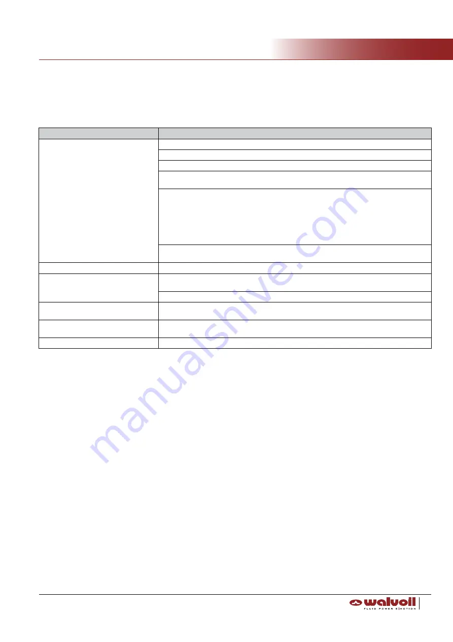
It is advisable to periodically check the parts shown in the table below.

___________________________________________________________________________

Standard maintenance rules

______________________________________________________________________________________________________

Disposal

Reference

Item to be checked

General installation

Verify valve is correctly and safely fixed in its seat

Check electric connector and wire condition and wear

Clean the valve carefully, avoiding direct jet, especially on electric parts and connections

In order to prevent rust, dry the valve after cleaning, avoiding scratching and damaging external 
surfaces
Periodically check the tightening of:
- Tie rods
- Lever box
- Control kit screws
- Unloading screw
- Electrohydraulic valve screws

- Hydraulic fittings
Constantly check oil  contamination status and plant filter condition.  Contamination may  bring to 

several malfunctions

Body

Check presence of excessive rust and corrosion and replace parts or complete valve if needed

Spool

Check presence of scratch, rust and corrosion. It may bring to seals damage or spool sticking. Re-
place parts if needed
Apply grease on spring, lever or positioning kits if the spool operation is not sliding

Sealing

Check and replace any possible hardened, de-formed or damaged O-ring. Check and replace the 
O-ring also in case its surface is dirty or shows particles.

LS Valve and Auxiliary Valves

Periodically check pressure setting values, if not correct adjust relief valves and safely lock the nut 

at appropriate torque

Electric components

Please refer to attached  service manual of these components

When the control valve has to be disposed, first drain the hydraulic fluid completely and dispose of it as industrial waste.

Summary of Contents for DPC130X

Page 1: ...DPC130X Pre compensated Load Sensing Sectional Valve ATEX version...

Page 2: ...FOR ANY RESULTING INJURY OR DAMAGE TO PERSONS OR PROPERTY Whenever the symbols shown below appear follow the instructions that are given Be sure to perform all operations and maintenance in complete...

Page 3: ...DPC130X _________________________________________________________________________________________ Table of contents Introduction page 4 Valve description page 5 General specifications page 9 Storage p...

Page 4: ...e product you must read this Service Manual carefully and understand its contents in order to prevent accidents or damages Do not carry out assembly disassembly and or maintenance activities before co...

Page 5: ..._____________________ Valve description Operating principle of Pre Compensated Load Sensing technology The main feature of this principle is that the flow rate to the user is proportional to the spool...

Page 6: ...to which Group the product belong and determine the category inside the Group Areas Gas Air type explosive mixture G Dust Air type explosive mixture D With the Atex Directive 2014 34 UE for the safety...

Page 7: ...tions for breakdown in case of explosion These products have to work in compliance with operative parameters established by the Manufacturer in environments with a high probabi lity of frequent or lon...

Page 8: ...0 60 C T fluid 20 80 C Via Adige 13 D 42124 Reggio E Italy CE mark DATAMATRIX ATEX mark manufacturer reference ATEX category environmental temperature fluid temperature E F 230 9 06 54 5 2 15 5 0 197...

Page 9: ...ng range from 15 to 75 mm2 s from 15 to 75 cSt min 12 mm2 s 12 cSt max 400 mm2 s 400 cSt Contamination level max 18 15 ISO 4406 NAS 1638 class 9 Environmental temperature for working conditions from 2...

Page 10: ...WARNING WARNING Cast iron O ring seals Parback Spring steel Other steel Other Cast iron EN GJl 250 NBR 70 Sh AISI 302 11SMnPb37 Sint A50 Cast iron EN GJL 300 VITON 75 Sh VDSiCr EN10270 2 16CrNi4Pb Ca...

Page 11: ...on of the hydraulic schema especially in case of electrohydraulic control be sure that drain line is directly connected to tank avoid any back pressure in case of variable displacement system be sure...

Page 12: ...case of the presence of electrohydraulic controls or unloading valve please cover these electronic parts as well as the cables before painting avoid painting the marking label for the electric parts...

Page 13: ...device before removing the hoses attach suitable indications on them so to be able to locate their positions later on It is also advisable to label dismounted parts and to write down their original l...

Page 14: ...ction screw by hand the tie rods from the side of shorter thread on the inlet section mount the working sections according to the scheme mount the outlet section put on the spring washers on the tie r...

Page 15: ...ces Periodically check the tightening of Tie rods Lever box Control kit screws Unloading screw Electrohydraulic valve screws Hydraulic fittings Constantly check oil contamination status and plant filt...

Page 16: ...WWW WALVOIL COM 1st edition September 2018 D1WWTD02E...

Reviews: