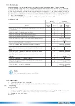
WALPOL WDV-A 355 EC Assembly And Operating Instructions Manual Download Page 15

15

13.3.  Maintenance

Only if maintenance has been carried out correctly and written proof of this is provided, is the warranty valid.

To ensure continuous fan operation, we recommend regular maintenance intervals. These maintenance intervals are de-

fined in the "Activities" table below. In addition, follow-up activities such as cleaning,replacement of defective components 

or other corrective measures must be carried out by the operator. For traceability, it is necessary to create a maintenance 

plan in which the work performed is documented. This must be prepared by the operator. If "extreme operating conditions" 

prevail, the maintenance intervals must be carried out at shorter intervals. Examples of extreme operating conditions:

• 

Fans for kitchen exhaust air

• 

Continuous ambient temperature > 30 ºC or < -10 ºC, or temperature fluctuations > 20 K 

Table 14 Activities

Normal

Operating conditions

Extreme

Operating conditions

Actions

Semian-

nual

Annual

Quar-

terly

Semian-

nual

Check the fan and its components for visible damage, corrosion and 

contamination.

X

X

Check the impeller for damage and imbalance.

X

X

Check the correct operation of the condensate drain.

X

X

X

Clean the fan/ventilation system (see 14 Cleaning).

X

X

Check the screw connections for tightness and for damage/defects.

X

see normal operating 

conditions

Make sure that the fan inlet is free of debris.

X

X

Check that the fan and its components are used as intended.

X

see normal operating 

conditions

Check the current consumption and compare it with the nominal 

data.

X

X

Check the vibration dampers (if used) for correct function, visible 

damage and corrosion.

X

see normal operating 

conditions

Check the electrical and mechanical protective devices for correct 

function.

X

see normal operating 

conditions

Check that the nameplate of the fan is legible.

X

X

Check the connection terminals and cable glands for tight fit and 

visible damage/defects.

X

see normal operating 

conditions

Check the flexible connectors for damage.

X

see normal operating 

conditions

Note

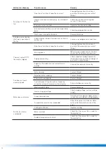
For all other damage/defects, please contact Walpol.

13.4.  Spare parts

• 

Only use original spare parts from Walpol!

• 

When ordering spare parts, specify the serial number of the fan. This is indicated on the nameplate.

14.  Cleaning

Safety instructions

• 

Cleaning may only be carried out by suitably qualified persons, for details see Table 1 Qualification.The 5 safety rules 

must be observed, see 2.3 The 5 safety rules for working in and on electrical installations.

• 

The impeller must be stationary.

Procedure

Summary of Contents for WDV-A 355 EC

Page 1: ...Roof fan TYPE WDV Assembly and operating instructions Version 6 1 B05...

Page 2: ...r data 7 5 5 Intended use 7 6 Nameplate and type key 7 7 Accessories 7 8 Installation 7 9 Installation of the ventilation system 8 9 1 Assembly disassembly of impeller internal rotor motor WDV A serie...

Page 3: ...ant conditions and requirements of the plant manufacturer or plant builder Safety devices must not be dismantled bypassed or rendered inoperative The fan may only be used when in perfect condition The...

Page 4: ...ipment Wear protective equipment during any work in the vicinity of the fan Protective clothing Safety shoes Protective gloves Safety helmet Safety goggles Hearing protection 2 3 The 5 safety rules fo...

Page 5: ...re that no water can penetrate the motor or other sensitive components It is recommended that the fan be transported to the installation site in its original packaging Caution Careless loading or unlo...

Page 6: ...e maximum fluid temperature is 60 C for series WDV K 5 3 Description roof fans A B E D C F G I J 4x H M20x1 5 Table dimensions roof fans TYPE A Dimen sions in mm WDV A 355 EC WDV A 400 EC WDV A 450 WD...

Page 7: ...air outlet discharge Motor in air flow Not suitable for commercial kitchens which must be executed according to VDI 2052 All types Improper use is mainly when the fan is used in a way other than desc...

Page 8: ...t the fan and all its components are undamaged Make sure that there is sufficient space for mounting the fan When mounting the device protect it from dust and moisture Make sure that the specification...

Page 9: ...ed directly before or after the fan A uniform and constant air flow to the unit must be ensured Free exhaust air must be ensured Rectangular duct system D Hydraulic diameter Round duct system D nomina...

Page 10: ...ble Allen key suitable extraction tool torque wrench for the clamping bush 1 Motor 2 Motor shaft 3 Sleeve Not used with every fan 4 Shaft extension Not used with every fan 5 Hexagon socket screw 6 Imp...

Page 11: ...ched on and off via the control input Screw down the cover of the terminal box revision switch evenly Use all locking screws Connect the cable end in a dry environment Install a permanent disconnectin...

Page 12: ...0 Hz The heating of the motor when using a frequency converter must be checked by the customer in the application Never exceed the maximum impeller speed specified on the fan nameplate 11 Commissionin...

Page 13: ...ructions for the motor 13 Troubleshooting Maintenance Repair 13 1 Safety instructions Troubleshooting maintenance repair may only be performed by appropriately qualified persons for details see Table...

Page 14: ...EC check that all 3 phases are present Engine overheating Check impeller cooling if present check resistance of motor windings if possible contact Walpol Capacitor if used not or not correctly con nec...

Page 15: ...Clean the fan ventilation system see 14 Cleaning X X Check the screw connections for tightness and for damage defects X see normal operating conditions Make sure that the fan inlet is free of debris X...

Page 16: ...material is recycled Observe the national regulations The device and the transport packaging consist mainly of recyclable raw materials Disassemble the fan into its component parts Separate the parts...

Page 17: ...control Transformer Frequency converter Sine filter Shielded cables Motor protection Yes No Motor protection switch or motor protection relay PTC thermistor Resistance value Thermal contact Electric...

Page 18: ...phase fans enter in line Current L1 A pressure between suction and discharge side of the fan If a volume flow measurement is not possible the value can be calculated using the following formula X Duc...

Reviews: